
Page 160 - Separation process engineering
P. 160
In Figure 4-8 we illustrated how to determine the optimum feed stage graphically. For computer
applications an explicit test is easier to use. If the point of intersection of the two operating lines (y , x ),
I
I
is determined, then the optimum feed plate, f, is the one for which
(4-37a)
and
(4-37b)
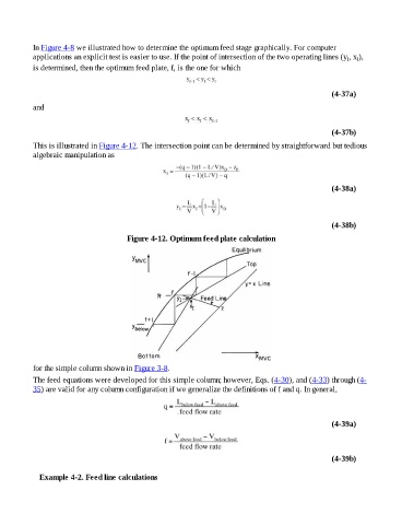
This is illustrated in Figure 4-12. The intersection point can be determined by straightforward but tedious
algebraic manipulation as
(4-38a)
(4-38b)
Figure 4-12. Optimum feed plate calculation
for the simple column shown in Figure 3-8.
The feed equations were developed for this simple column; however, Eqs. (4-30), and (4-33) through (4-
35) are valid for any column configuration if we generalize the definitions of f and q. In general,
(4-39a)
(4-39b)
Example 4-2. Feed line calculations