
Page 165 - Separation process engineering
P. 165
Alternative solution: Intersection of top operating line and y = x (solve top operating line and y = x
simultaneously) is at y = x = x . The top operating line is plotted in Figure 4-13.
D
Bottom Operating Line:
We know that the bottom operating line intersects the top operating line at the feed line; this is one
point. We could calculate / from mass balances or from Eq. (4-25), but it easier to find another
point. The intersection of the bottom operating line and the y = x line is at y = x = x (see Problem
B
4.C9). This gives a second point.
The feed line, top operating line, and bottom operating line are shown in Figure 4-13. We stepped
off stages from the bottom up (this is an arbitrary choice). The optimum feed stage is the second
above the partial reboiler. 12 equilibrium stages plus a partial reboiler are required.
E. Check. We have a built-in check on the top operating line, since a slope and two points are
calculated. The bottom operating line can be checked by calculating / from mass balances and
comparing it to the slope. The numbers are reasonable, since L/V < 1, / > 1, and q > 1 as
expected. The most likely cause of error in Figure 4-13 (and the hardest to check) is the
equilibrium data.
F. Generalization. If constructed carefully, the McCabe-Thiele diagram is quite accurate. Note that
there is no need to plot parts of the equilibrium diagram that are greater than x or less than x .
D
B
Specified parts of the diagram can be expanded to increase the accuracy.
We did not have to use external balances in this example, while in Example 4-1 we did. This is because
we used the feed line as an aid in finding the bottom operating line. The y = x intersection points are
useful, but when the column configuration is changed their location may change.
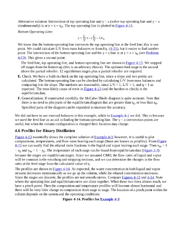
4.6 Profiles for Binary Distillation
Figure 4-13 essentially shows the complete solution of Example 4-3; however, it is useful to plot
compositions, temperatures, and flow rates leaving each stage (these are known as profiles). From Figure
4-13 we can easily find the ethanol mole fractions in the liquid and vapor leaving each stage. Then x = 1
W
− x and y = 1 − y . The temperature of each stage can be found from equilibrium data (Figure 2-3)
W
E
E
because the stages are equilibrium stages. Since we assumed CMO, the flow rates of liquid and vapor
will be constant in the enriching and stripping sections, and we can determine the changes in the flow
rates at the feed stage from the calculated value of q.
The profiles are shown in Figure 4-14. As expected, the water concentration in both liquid and vapor
streams decreases monotonically as we go up the column, while the ethanol concentration increases.
Since the stages are discrete, the profiles are not smooth curves. Compare Figures 4-13 and 4-14. Note
where the operating line and equilibrium curve are close together. When these two lines almost touch, we
have a pinch point. Then the composition and temperature profiles will become almost horizontal and
there will be very little change in composition from stage to stage. The location of a pinch point within the
column depends on the system and the operating conditions.
Figure 4-14. Profiles for Example 4-3