
Page 109 - Shale Shakers Drilling Fluid Systems
P. 109
92 SHALE SHAKERS AND DRILLING FLUID SYSTEMS
HOW A SHALE SHAKER SCREENS FLUID
Shale shakers should remove as many drilled
solids and as little drilling fluid as possible. These
dual objectives require that cuttings (or drilled
solids) convey off the screen while simultaneously
separating and removing most of the drilling fluid
from the cuttings. Frequently, the only stated
objective of a shale shaker is to remove the
maximum quantity of drilled solids. Disregarding
the need to conserve as much drilling fluid as pos-
sible defeats the ultimate objective of reducing
drilling costs.
Cutting sizes greatly influence the quantity of
drilling fluid that tends to adhere to the solids. As
an extreme example, consider a golfball-size drilled
solid coated with drilling fluid. Even with a viscous
fluid, the volume of fluid would be very small
compared with the volume of the solid. If the sol-
ids are sand-sized, the fluid-film volume increases
as the solids surface area increases. For silt-size FIGURE 2-1
or ultra-fine solids, the volume of liquid coating
the solids may even be larger than the solids vol-
ume. More drilling fluid returns to the system
when very coarse screens are used than when
screens as fine as 200 mesh are used.
Drilling fluid is a Theologically complex system.
At the bottom of the hole, faster drilling is pos-
sible if the fluid has a low viscosity. In the annu-
lus, drilled solids are transported better if the fluid
has a high viscosity. When the flow stops, a gel
structure slowly builds to prevent cuttings or weight-
ing agents from settling. Drilling fluid is usually
constructed to perform these functions. This means
that the fluid viscosity depends on the history and
shear within the fluid. Typically, low-shear-rate
viscosities of drilling fluids range from 300 to 400
centipoise up to 1000 to 1500 centipoise. As the
shear rate (or usually the velocity) increases, drill-
ing fluid viscosity decreases. Even with a low-
shear-rate viscosity of 1500 centipoise, the plastic
viscosity (or high-shear-rate viscosity) could be as
low as 10 centipoise.
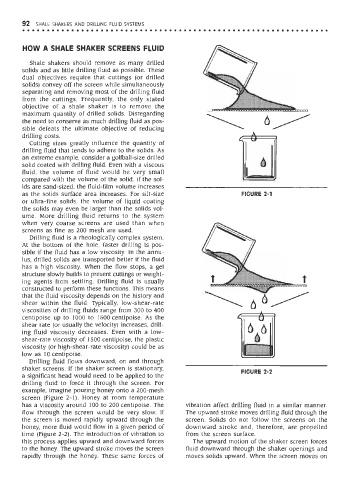
Drilling fluid flows downward, on and through
shaker screens. If the shaker screen is stationary, FIGURE 2-2
a significant head would need to be applied to the
drilling fluid to force it through the screen. For
example, imagine pouring honey onto a 200-mesh
screen (Figure 2-1). Honey at room temperature
has a viscosity around 100 to 200 centipoise. The vibration affect drilling fluid in a similar manner.
flow through the screen would be very slow. If The upward stroke moves drilling fluid through the
the screen is moved rapidly upward through the screen. Solids do not follow the screens on the
honey, more fluid would flow in a given period of downward stroke and, therefore, are propelled
time (Figure 2-2). The introduction of vibration to from the screen surface.
this process applies upward and downward forces The upward motion of the shaker screen forces
to the honey. The upward stroke moves the screen fluid downward through the shaker openings and
rapidly through the honey. These same forces of moves solids upward. When the screen moves on