
Page 286 - Shigley's Mechanical Engineering Design
P. 286
bud29281_ch05_212-264.qxd 11/27/2009 6:46 pm Page 261 pinnacle s-171:Desktop Folder:Temp Work:Don't Delete (Jobs):MHDQ196/Budynas:
Failures Resulting from Static Loading 261
for Prob. 3–40. The pin is machined from AISI 1018 hot-rolled steel. Compare the three models
from a designer’s perspective in terms of accuracy, safety, and modeling time.
5–66* For the clevis pin of Prob. 3–40, p. 132, redesign the pin diameter to provide a factor of safety of
2.5 based on a conservative yielding failure theory, and the most conservative loading model from
parts c, d, and e of the figure for Prob. 3–40. The pin is machined from AISI 1018 hot-rolled steel.
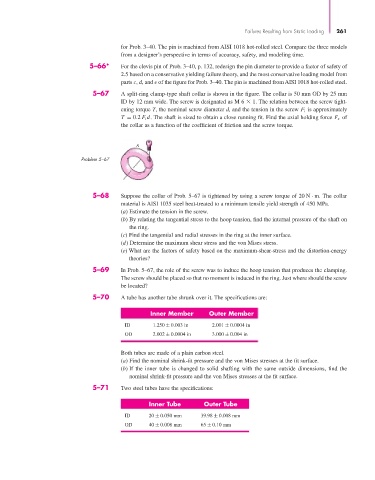
5–67 A split-ring clamp-type shaft collar is shown in the figure. The collar is 50 mm OD by 25 mm
ID by 12 mm wide. The screw is designated as M 6 1. The relation between the screw tight-
ening torque T, the nominal screw diameter d, and the tension in the screw F i is approximately
T = 0.2 F i d. The shaft is sized to obtain a close running fit. Find the axial holding force F x of
the collar as a function of the coefficient of friction and the screw torque.
A
Problem 5–67
5–68 Suppose the collar of Prob. 5–67 is tightened by using a screw torque of 20 N · m. The collar
material is AISI 1035 steel heat-treated to a minimum tensile yield strength of 450 MPa.
(a) Estimate the tension in the screw.
(b) By relating the tangential stress to the hoop tension, find the internal pressure of the shaft on
the ring.
(c) Find the tangential and radial stresses in the ring at the inner surface.
(d) Determine the maximum shear stress and the von Mises stress.
(e) What are the factors of safety based on the maximum-shear-stress and the distortion-energy
theories?
5–69 In Prob. 5–67, the role of the screw was to induce the hoop tension that produces the clamping.
The screw should be placed so that no moment is induced in the ring. Just where should the screw
be located?
5–70 A tube has another tube shrunk over it. The specifications are:
Inner Member Outer Member
ID 1.250 ± 0.003 in 2.001 ± 0.0004 in
OD 2.002 ± 0.0004 in 3.000 ± 0.004 in
Both tubes are made of a plain carbon steel.
(a) Find the nominal shrink-fit pressure and the von Mises stresses at the fit surface.
(b) If the inner tube is changed to solid shafting with the same outside dimensions, find the
nominal shrink-fit pressure and the von Mises stresses at the fit surface.
5–71 Two steel tubes have the specifications:
Inner Tube Outer Tube
ID 20 ± 0.050 mm 39.98 ± 0.008 mm
OD 40 ± 0.008 mm 65 ± 0.10 mm