
Page 387 - Shigley's Mechanical Engineering Design
P. 387
bud29281_ch07_358-408.qxd 12/8/09 12:52PM Page 362 ntt 203:MHDQ196:bud29281:0073529281:bud29281_pagefiles:
362 Mechanical Engineering Design
Figure 7–1
A vertical worm-gear speed
reducer. (Courtesy of the
Cleveland Gear Company.)
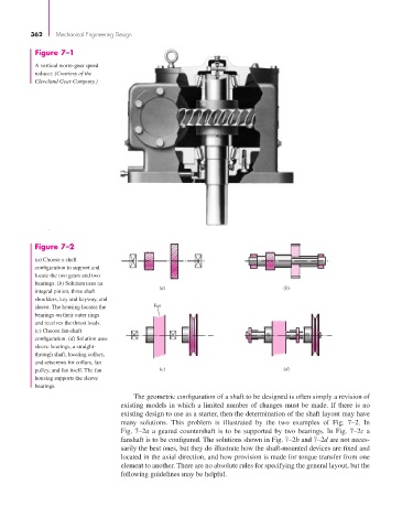
Figure 7–2
(a) Choose a shaft
configuration to support and
locate the two gears and two
bearings. (b) Solution uses an
(a) (b)
integral pinion, three shaft
shoulders, key and keyway, and
sleeve. The housing locates the Fan
bearings on their outer rings
and receives the thrust loads.
(c) Choose fan-shaft
configuration. (d) Solution uses
sleeve bearings, a straight-
through shaft, locating collars,
and setscrews for collars, fan
pulley, and fan itself. The fan (c) (d)
housing supports the sleeve
bearings.
The geometric configuration of a shaft to be designed is often simply a revision of
existing models in which a limited number of changes must be made. If there is no
existing design to use as a starter, then the determination of the shaft layout may have
many solutions. This problem is illustrated by the two examples of Fig. 7–2. In
Fig. 7–2a a geared countershaft is to be supported by two bearings. In Fig. 7–2c a
fanshaft is to be configured. The solutions shown in Fig. 7–2b and 7–2d are not neces-
sarily the best ones, but they do illustrate how the shaft-mounted devices are fixed and
located in the axial direction, and how provision is made for torque transfer from one
element to another. There are no absolute rules for specifying the general layout, but the
following guidelines may be helpful.