
Page 390 - Shigley's Mechanical Engineering Design
P. 390
bud29281_ch07_358-408.qxd 12/8/09 12:52PM Page 365 ntt 203:MHDQ196:bud29281:0073529281:bud29281_pagefiles:
Shafts and Shaft Components 365
Splines are essentially stubby gear teeth formed on the outside of the shaft and on
the inside of the hub of the load-transmitting component. Splines are generally much
more expensive to manufacture than keys, and are usually not necessary for simple
torque transmission. They are typically used to transfer high torques. One feature of a
spline is that it can be made with a reasonably loose slip fit to allow for large axial
motion between the shaft and component while still transmitting torque. This is useful
for connecting two shafts where relative motion between them is common, such as in
connecting a power takeoff (PTO) shaft of a tractor to an implement. SAE and ANSI
publish standards for splines. Stress-concentration factors are greatest where the spline
ends and blends into the shaft, but are generally quite moderate.
For cases of low torque transmission, various means of transmitting torque are
available. These include pins, setscrews in hubs, tapered fits, and press fits.
Press and shrink fits for securing hubs to shafts are used both for torque transfer
and for preserving axial location. The resulting stress-concentration factor is usually
quite small. See Sec. 7–8 for guidelines regarding appropriate sizing and tolerancing to
transmit torque with press and shrink fits. A similar method is to use a split hub with
screws to clamp the hub to the shaft. This method allows for disassembly and lateral
adjustments. Another similar method uses a two-part hub consisting of a split inner
member that fits into a tapered hole. The assembly is then tightened to the shaft with
screws, which forces the inner part into the wheel and clamps the whole assembly
against the shaft.
Tapered fits between the shaft and the shaft-mounted device, such as a wheel, are
often used on the overhanging end of a shaft. Screw threads at the shaft end then permit
the use of a nut to lock the wheel tightly to the shaft. This approach is useful because it
can be disassembled, but it does not provide good axial location of the wheel on the shaft.
At the early stages of the shaft layout, the important thing is to select an appro-
priate means of transmitting torque, and to determine how it affects the overall shaft
layout. It is necessary to know where the shaft discontinuities, such as keyways, holes,
and splines, will be in order to determine critical locations for analysis.
Assembly and Disassembly
Consideration should be given to the method of assembling the components onto the
shaft, and the shaft assembly into the frame. This generally requires the largest diame-
ter in the center of the shaft, with progressively smaller diameters towards the ends to
allow components to be slid on from the ends. If a shoulder is needed on both sides of
a component, one of them must be created by such means as a retaining ring or by a
sleeve between two components. The gearbox itself will need means to physically posi-
tion the shaft into its bearings, and the bearings into the frame. This is typically accom-
plished by providing access through the housing to the bearing at one end of the shaft.
See Figs. 7–5 through 7–8 for examples.
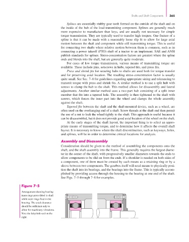
Figure 7–5
Arrangement showing bearing
inner rings press-fitted to shaft
while outer rings float in the
housing. The axial clearance
should be sufficient only to
allow for machinery vibrations.
Note the labyrinth seal on the
right.