
Page 392 - Shigley's Mechanical Engineering Design
P. 392
bud29281_ch07_358-408.qxd 12/8/09 12:52PM Page 367 ntt 203:MHDQ196:bud29281:0073529281:bud29281_pagefiles:
Shafts and Shaft Components 367
Most shafts will transmit torque through a portion of the shaft. Typically the torque
comes into the shaft at one gear and leaves the shaft at another gear. A free body dia-
gram of the shaft will allow the torque at any section to be determined. The torque is
often relatively constant at steady state operation. The shear stress due to the torsion
will be greatest on outer surfaces.
The bending moments on a shaft can be determined by shear and bending moment
diagrams. Since most shaft problems incorporate gears or pulleys that introduce forces
in two planes, the shear and bending moment diagrams will generally be needed in two
planes. Resultant moments are obtained by summing moments as vectors at points of
interest along the shaft. The phase angle of the moments is not important since the
shaft rotates. A steady bending moment will produce a completely reversed moment
on a rotating shaft, as a specific stress element will alternate from compression to
tension in every revolution of the shaft. The normal stress due to bending moments
will be greatest on the outer surfaces. In situations where a bearing is located at the
end of the shaft, stresses near the bearing are often not critical since the bending
moment is small.
Axial stresses on shafts due to the axial components transmitted through helical
gears or tapered roller bearings will almost always be negligibly small compared to
the bending moment stress. They are often also constant, so they contribute little to
fatigue. Consequently, it is usually acceptable to neglect the axial stresses induced by
the gears and bearings when bending is present in a shaft. If an axial load is applied
to the shaft in some other way, it is not safe to assume it is negligible without check-
ing magnitudes.
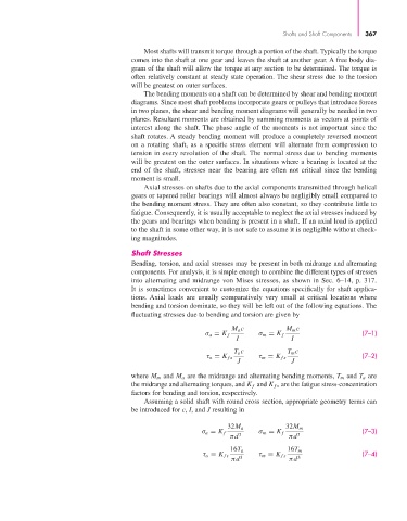
Shaft Stresses
Bending, torsion, and axial stresses may be present in both midrange and alternating
components. For analysis, it is simple enough to combine the different types of stresses
into alternating and midrange von Mises stresses, as shown in Sec. 6–14, p. 317.
It is sometimes convenient to customize the equations specifically for shaft applica-
tions. Axial loads are usually comparatively very small at critical locations where
bending and torsion dominate, so they will be left out of the following equations. The
fluctuating stresses due to bending and torsion are given by
M a c M m c
σ a = K f σ m = K f (7–1)
I I
T a c T m c
τ a = K fs τ m = K fs (7–2)
J J
where M m and M a are the midrange and alternating bending moments, T m and T a are
the midrange and alternating torques, and K f and K fs are the fatigue stress-concentration
factors for bending and torsion, respectively.
Assuming a solid shaft with round cross section, appropriate geometry terms can
be introduced for c, I, and J resulting in
32M a 32M m
σ a = K f σ m = K f (7–3)
πd 3 πd 3
16T a 16T m
τ a = K fs τ m = K fs (7–4)
πd 3 πd 3