
Page 397 - Shigley's Mechanical Engineering Design
P. 397
bud29281_ch07_358-408.qxd 12/8/09 12:52PM Page 372 ntt 203:MHDQ196:bud29281:0073529281:bud29281_pagefiles:
372 Mechanical Engineering Design
For comparison, a quick and very conservative check on yielding can be obtained
by replacing σ with σ + σ . This just saves the extra time of calculating σ if
max a m max
σ and σ have already been determined. For this example,
a m
S y 82 000
n y = = = 3.25
σ + σ 15 235 + 9988
a m
which is quite conservative compared with n y 4.50.
Estimating Stress Concentrations
The stress analysis process for fatigue is highly dependent on stress concentrations.
Stress concentrations for shoulders and keyways are dependent on size specifications
that are not known the first time through the process. Fortunately, since these elements
are usually of standard proportions, it is possible to estimate the stress-concentration
factors for initial design of the shaft. These stress concentrations will be fine-tuned in
successive iterations, once the details are known.
Shoulders for bearing and gear support should match the catalog recommendation
for the specific bearing or gear. A look through bearing catalogs shows that a typical
bearing calls for the ratio of D/d to be between 1.2 and 1.5. For a first approximation,
the worst case of 1.5 can be assumed. Similarly, the fillet radius at the shoulder needs
to be sized to avoid interference with the fillet radius of the mating component. There is
a significant variation in typical bearings in the ratio of fillet radius versus bore diameter,
with r/d typically ranging from around 0.02 to 0.06. A quick look at the stress con-
centration charts (Figures A–15–8 and A–15–9) shows that the stress concentrations for
bending and torsion increase significantly in this range. For example, with D/d = 1.5
for bending, K t = 2.7 at r/d = 0.02, and reduces to K t = 2.1 at r/d = 0.05, and
further down to K t = 1.7 at r/d = 0.1. This indicates that this is an area where some
attention to detail could make a significant difference. Fortunately, in most cases the
shear and bending moment diagrams show that bending moments are quite low near
the bearings, since the bending moments from the ground reaction forces are small.
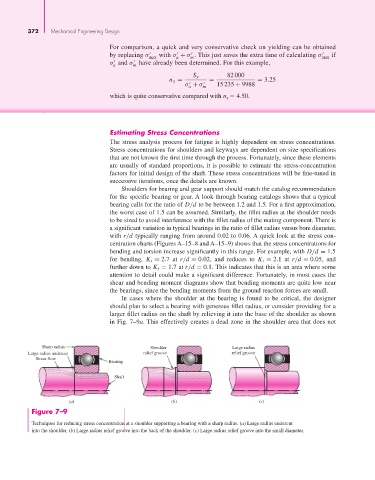
In cases where the shoulder at the bearing is found to be critical, the designer
should plan to select a bearing with generous fillet radius, or consider providing for a
larger fillet radius on the shaft by relieving it into the base of the shoulder as shown
in Fig. 7–9a. This effectively creates a dead zone in the shoulder area that does not
Sharp radius Shoulder Large radius
Large radius undercut relief groove relief groove
Stress flow
Bearing
Shaft
(a) (b) (c)
Figure 7–9
Techniques for reducing stress concentration at a shoulder supporting a bearing with a sharp radius. (a) Large radius undercut
into the shoulder. (b) Large radius relief groove into the back of the shoulder. (c) Large radius relief groove into the small diameter.