
Page 398 - Shigley's Mechanical Engineering Design
P. 398
bud29281_ch07_358-408.qxd 12/8/09 12:52PM Page 373 ntt 203:MHDQ196:bud29281:0073529281:bud29281_pagefiles:
Shafts and Shaft Components 373
carry the bending stresses, as shown by the stress flow lines. A shoulder relief groove
as shown in Fig. 7–9b can accomplish a similar purpose. Another option is to cut a
large-radius relief groove into the small diameter of the shaft, as shown in Fig. 7–9c.
This has the disadvantage of reducing the cross-sectional area, but is often used in cases
where it is useful to provide a relief groove before the shoulder to prevent the grinding
or turning operation from having to go all the way to the shoulder.
For the standard shoulder fillet, for estimating K t values for the first iteration,
an r/d ratio should be selected so K t values can be obtained. For the worst end
of the spectrum, with r/d = 0.02 and D/d = 1.5, K t values from the stress
concentration charts for shoulders indicate 2.7 for bending, 2.2 for torsion, and 3.0
for axial.
A keyway will produce a stress concentration near a critical point where the load-
transmitting component is located. The stress concentration in an end-milled keyseat
is a function of the ratio of the radius r at the bottom of the groove and the shaft
diameter d. For early stages of the design process, it is possible to estimate the stress
concentration for keyways regardless of the actual shaft dimensions by assuming a
typical ratio of r/d = 0.02. This gives K t = 2.14 for bending and K ts = 3.0 for
torsion, assuming the key is in place.
Figures A–15–16 and A–15–17 give values for stress concentrations for flat-
bottomed grooves such as used for retaining rings. By examining typical retaining
ring specifications in vendor catalogs, it can be seen that the groove width is typically
slightly greater than the groove depth, and the radius at the bottom of the groove is
around 1/10 of the groove width. From Figs. A–15–16 and A–15–17, stress-concentration
factors for typical retaining ring dimensions are around 5 for bending and axial, and 3
for torsion. Fortunately, the small radius will often lead to a smaller notch sensitivity,
reducing K f .
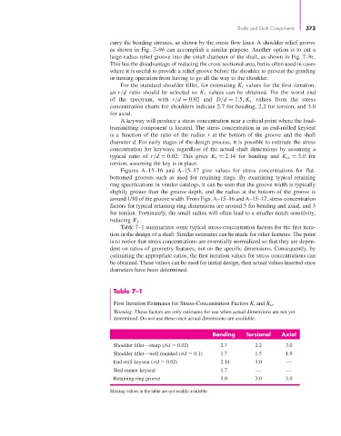
Table 7–1 summarizes some typical stress-concentration factors for the first itera-
tion in the design of a shaft. Similar estimates can be made for other features. The point
is to notice that stress concentrations are essentially normalized so that they are depen-
dent on ratios of geometry features, not on the specific dimensions. Consequently, by
estimating the appropriate ratios, the first iteration values for stress concentrations can
be obtained. These values can be used for initial design, then actual values inserted once
diameters have been determined.
Table 7–1
First Iteration Estimates for Stress-Concentration Factors K t and K ts .
Warning: These factors are only estimates for use when actual dimensions are not yet
determined. Do not use these once actual dimensions are available.
Bending Torsional Axial
Shoulder fillet—sharp (r/d 0.02) 2.7 2.2 3.0
Shoulder fillet—well rounded (r/d 0.1) 1.7 1.5 1.9
End-mill keyseat (r/d 0.02) 2.14 3.0 —
Sled runner keyseat 1.7 — —
Retaining ring groove 5.0 3.0 5.0
Missing values in the table are not readily available.