
Page 399 - Shigley's Mechanical Engineering Design
P. 399
bud29281_ch07_358-408.qxd 12/8/09 12:52PM Page 374 ntt 203:MHDQ196:bud29281:0073529281:bud29281_pagefiles:
374 Mechanical Engineering Design
EXAMPLE 7–2
This example problem is part of a larger case study. See Chap. 18 for the full
context.
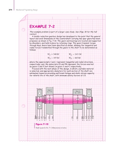
A double reduction gearbox design has developed to the point that the general
layout and axial dimensions of the countershaft carrying two spur gears has been
proposed, as shown in Fig. 7–10. The gears and bearings are located and supported
by shoulders, and held in place by retaining rings. The gears transmit torque
through keys. Gears have been specified as shown, allowing the tangential and
radial forces transmitted through the gears to the shaft to be determined as
follows.
W t = 540 lbf W t = 2431 lbf
23 54
W r = 197 lbf W r = 885 lbf
23 54
where the superscripts t and r represent tangential and radial directions,
respectively; and, the subscripts 23 and 54 represent the forces exerted
by gears 2 and 5 (not shown) on gears 3 and 4, respectively.
Proceed with the next phase of the design, in which a suitable material
is selected, and appropriate diameters for each section of the shaft are
estimated, based on providing sufficient fatigue and static stress capacity
for infinite life of the shaft, with minimum safety factors of 1.5.
Bearing A Bearing B
Gear 3
d 3 12 Gear 4
d 4 2.67
D 3 D 5
D 1 D 2 D 4 D 6 D 7
Datum 0.25 0.75 1.25 1.75 2.0 2.75 3.50 7.50 8.50 9.50 9.75 10.25 10.75 11.25 11.50
CA D E F G H I J K L M B N
Figure 7–10
Shaft layout for Ex. 7–2. Dimensions in inches.