
Page 404 - Shigley's Mechanical Engineering Design
P. 404
bud29281_ch07_358-408.qxd 12/9/09 4:29PM Page 379 ntt 203:MHDQ196:bud29281:0073529281:bud29281_pagefiles:
Shafts and Shaft Components 379
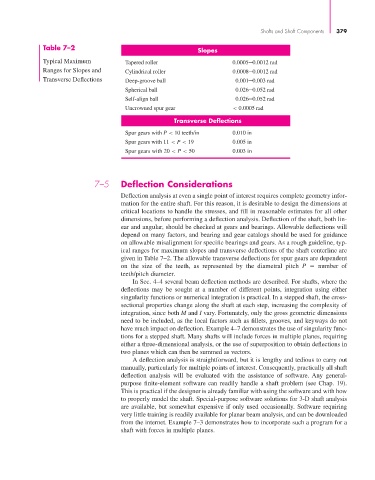
Table 7–2
Slopes
Typical Maximum Tapered roller 0.0005–0.0012 rad
Ranges for Slopes and Cylindrical roller 0.0008–0.0012 rad
Transverse Deflections Deep-groove ball 0.001–0.003 rad
Spherical ball 0.026–0.052 rad
Self-align ball 0.026–0.052 rad
Uncrowned spur gear < 0.0005 rad
Transverse Deflections
Spur gears with P < 10 teeth/in 0.010 in
Spur gears with 11 < P < 19 0.005 in
Spur gears with 20 < P < 50 0.003 in
7–5 Deflection Considerations
Deflection analysis at even a single point of interest requires complete geometry infor-
mation for the entire shaft. For this reason, it is desirable to design the dimensions at
critical locations to handle the stresses, and fill in reasonable estimates for all other
dimensions, before performing a deflection analysis. Deflection of the shaft, both lin-
ear and angular, should be checked at gears and bearings. Allowable deflections will
depend on many factors, and bearing and gear catalogs should be used for guidance
on allowable misalignment for specific bearings and gears. As a rough guideline, typ-
ical ranges for maximum slopes and transverse deflections of the shaft centerline are
given in Table 7–2. The allowable transverse deflections for spur gears are dependent
on the size of the teeth, as represented by the diametral pitch P number of
teeth/pitch diameter.
In Sec. 4–4 several beam deflection methods are described. For shafts, where the
deflections may be sought at a number of different points, integration using either
singularity functions or numerical integration is practical. In a stepped shaft, the cross-
sectional properties change along the shaft at each step, increasing the complexity of
integration, since both M and I vary. Fortunately, only the gross geometric dimensions
need to be included, as the local factors such as fillets, grooves, and keyways do not
have much impact on deflection. Example 4–7 demonstrates the use of singularity func-
tions for a stepped shaft. Many shafts will include forces in multiple planes, requiring
either a three-dimensional analysis, or the use of superposition to obtain deflections in
two planes which can then be summed as vectors.
A deflection analysis is straightforward, but it is lengthy and tedious to carry out
manually, particularly for multiple points of interest. Consequently, practically all shaft
deflection analysis will be evaluated with the assistance of software. Any general-
purpose finite-element software can readily handle a shaft problem (see Chap. 19).
This is practical if the designer is already familiar with using the software and with how
to properly model the shaft. Special-purpose software solutions for 3-D shaft analysis
are available, but somewhat expensive if only used occasionally. Software requiring
very little training is readily available for planar beam analysis, and can be downloaded
from the internet. Example 7–3 demonstrates how to incorporate such a program for a
shaft with forces in multiple planes.