
Page 405 - Shigley's Mechanical Engineering Design
P. 405
bud29281_ch07_358-408.qxd 12/8/09 12:52PM Page 380 ntt 203:MHDQ196:bud29281:0073529281:bud29281_pagefiles:
380 Mechanical Engineering Design
EXAMPLE 7–3
This example problem is part of a larger case study. See Chap. 18 for the full
context.
In Ex. 7–2, a preliminary shaft geometry was obtained on the basis of design
for stress. The resulting shaft is shown in Fig. 7–10, with proposed diameters of
D 1 = D 7 = 1 in
D 2 = D 6 = 1.4 in
D 3 = D 5 = 1.625 in
D 4 = 2.0 in
Check that the deflections and slopes at the gears and bearings are acceptable. If
necessary, propose changes in the geometry to resolve any problems.
Solution
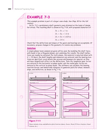
A simple planar beam analysis program will be used. By modeling the shaft twice,
with loads in two orthogonal planes, and combining the results, the shaft deflec-
tions can readily be obtained. For both planes, the material is selected (steel with
E = 30 Mpsi), the shaft lengths and diameters are entered, and the bearing loca-
tions are specified. Local details like grooves and keyways are ignored, as they
will have insignificant effect on the deflections. Then the tangential gear forces
are entered in the horizontal xz plane model, and the radial gear forces are
entered in the vertical xy plane model. The software can calculate the bearing
reaction forces, and numerically integrate to generate plots for shear, moment,
slope, and deflection, as shown in Fig. 7–11.
xy plane xz plane
Beam length: 11.5 in Beam length: 11.5 in
in in
Deflection Deflection
deg deg
Slope Slope
lbf-in lbf-in
Moment Moment
lbf lbf
Shear Shear
Figure 7–11
Shear, moment, slope, and deflection plots from two planes. (Source: Beam 2D Stress Analysis, Orand
Systems, Inc.)