Page 406 - Shigley's Mechanical Engineering Design
P. 406

bud29281_ch07_358-408.qxd  12/9/09  4:29PM  Page 381 ntt 203:MHDQ196:bud29281:0073529281:bud29281_pagefiles:


                                                                                          Shafts and Shaft Components  381


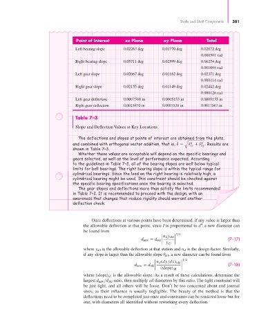
                                           Point of Interest     xz Plane         xy Plane            Total
                                           Left bearing slope    0.02263 deg      0.01770 deg      0.02872 deg
                                                                                                   0.000501 rad
                                           Right bearing slope   0.05711 deg      0.02599 deg      0.06274 deg
                                                                                                   0.001095 rad
                                           Left gear slope       0.02067 deg      0.01162 deg      0.02371 deg
                                                                                                   0.000414 rad
                                           Right gear slope      0.02155 deg      0.01149 deg      0.02442 deg
                                                                                                   0.000426 rad
                                           Left gear deflection   0.0007568 in     0.0005153 in     0.0009155 in
                                           Right gear deflection  0.0015870 in     0.0007535 in     0.0017567 in

                                           Table 7–3

                                           Slope and Deflection Values at Key Locations

                                            The deflections and slopes at points of interest are obtained from the plots,

                                                                                                   2
                                                                                              2
                                          and combined with orthogonal vector addition, that is, δ =  δ + δ . Results are
                                                                                              xz   xy
                                          shown in Table 7–3.
                                            Whether these values are acceptable will depend on the specific bearings and
                                          gears selected, as well as the level of performance expected. According
                                          to the guidelines in Table 7–2, all of the bearing slopes are well below typical
                                          limits for ball bearings. The right bearing slope is within the typical range for
                                          cylindrical bearings. Since the load on the right bearing is relatively high, a
                                          cylindrical bearing might be used. This constraint should be checked against
                                          the specific bearing specifications once the bearing is selected.
                                            The gear slopes and deflections more than satisfy the limits recommended
                                          in Table 7–2. It is recommended to proceed with the design, with an
                                          awareness that changes that reduce rigidity should warrant another
                                          deflection check.


                                                  Once deflections at various points have been determined, if any value is larger than
                                                                                                   4
                                               the allowable deflection at that point, since I is proportional to d , a new diameter can
                                               be found from
                                                                                         1/4
                                                                                   n d y old
                                                                                                               (7–17)

                                                                                    y all
                                                                        d new = d old
                                               where y all is the allowable deflection at that station and n d is the design factor. Similarly,
                                               if any slope is larger than the allowable slope θ all , a new diameter can be found from
                                                                                            1/4
                                                                                n d (dy/dx) old
                                                                                                               (7–18)

                                                                                 (slope) all
                                                                      d new = d old
                                               where (slope) all is the allowable slope. As a result of these calculations, determine the
                                               largest d new /d old ratio, then multiply all diameters by this ratio. The tight constraint will
                                               be just tight, and all others will be loose. Don’t be too concerned about end journal
                                               sizes, as their influence is usually negligible. The beauty of the method is that the
                                               deflections need to be completed just once and constraints can be rendered loose but for
                                               one, with diameters all identified without reworking every deflection.
   401   402   403   404   405   406   407   408   409   410   411