
Page 411 - Shigley's Mechanical Engineering Design
P. 411
bud29281_ch07_358-408.qxd 12/8/09 12:52PM Page 386 ntt 203:MHDQ196:bud29281:0073529281:bud29281_pagefiles:
386 Mechanical Engineering Design
This is called Dunkerley’s equation. By ignoring the higher mode term(s), the first
critical speed estimate is lower than actually is the case.
Since Eq. (7–32) has no loads appearing in the equation, it follows that if each load
could be placed at some convenient location transformed into an equivalent load, then
the critical speed of an array of loads could be found by summing the equivalent loads,
all placed at a single convenient location. For the load at station 1, placed at the center
of span, denoted with the subscript c, the equivalent load is found from
1 g g
2
ω = = =
11
m 1 δ 11 w 1 δ 11 w 1c δ cc
or
δ 11
w 1c = w 1 (7–33)
δ cc
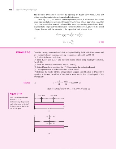
EXAMPLE 7–5 Consider a simply supported steel shaft as depicted in Fig. 7–14, with 1 in diameter and
a 31-in span between bearings, carrying two gears weighing 35 and 55 lbf.
(a) Find the influence coefficients.
2
(b) Find % wy and % wy and the first critical speed using Rayleigh’s equation,
Eq. (7–23).
(c) From the influence coefficients, find ω 11 and ω 22 .
(d) Using Dunkerley’s equation, Eq. (7–32), estimate the first critical speed.
(e) Use superposition to estimate the first critical speed.
(f ) Estimate the shaft’s intrinsic critical speed. Suggest a modification to Dunkerley’s
equation to include the effect of the shaft’s mass on the first critical speed of the
attachments.
πd 4 π(1) 4
Solution (a) I = = = 0.049 09 in 4
64 64
6
9
6EIl = 6(30)10 (0.049 09)31 = 0.2739(10 ) lbf · in 3
Figure 7–14 y
w = 35 lbf w = 55 lbf
2
1
(a) A 1-in uniform-diameter
7 in 13 in 11 in
shaft for Ex. 7–5.
(b) Superposing of equivalent
loads at the center of the shaft x
for the purpose of finding the
first critical speed. 31 in
(a)
y
w 1c 17.1 lbf
15.5 in 15.5 in
w 2c 46.1 lbf
x
(b)