
Page 415 - Shigley's Mechanical Engineering Design
P. 415
bud29281_ch07_358-408.qxd 12/8/09 12:52PM Page 390 ntt 203:MHDQ196:bud29281:0073529281:bud29281_pagefiles:
390 Mechanical Engineering Design
thrust, and the tangential holding power, for resisting torsion. Typical factors of safety
are 1.5 to 2.0 for static loads and 4 to 8 for various dynamic loads.
Setscrews should have a length of about half of the shaft diameter. Note that this
practice also provides a rough rule for the radial thickness of a hub or collar.
Keys and Pins
Keys and pins are used on shafts to secure rotating elements, such as gears, pulleys, or
other wheels. Keys are used to enable the transmission of torque from the shaft to the
shaft-supported element. Pins are used for axial positioning and for the transfer of
torque or thrust or both.
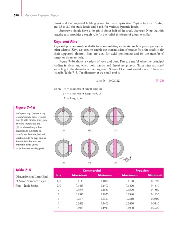
Figure 7–16 shows a variety of keys and pins. Pins are useful when the principal
loading is shear and when both torsion and thrust are present. Taper pins are sized
according to the diameter at the large end. Some of the most useful sizes of these are
listed in Table 7–5. The diameter at the small end is
d = D − 0.0208L (7–35)
where d diameter at small end, in
D diameter at large end, in
L length, in
Figure 7–16
(a) Square key; (b) round key;
(c and d) round pins; (e) taper
pin; (f) split tubular spring pin.
The pins in parts (e) and
( f) are shown longer than
necessary, to illustrate the (a) (b) (c)
chamfer on the ends, but their
lengths should be kept smaller
than the hub diameters to
prevent injuries due to
projections on rotating parts.
(d) (e) ( f)
Table 7–5 Commercial Precision
Size Maximum Minimum Maximum Minimum
Dimensions at Large End
of Some Standard Taper 4/0 0.1103 0.1083 0.1100 0.1090
Pins—Inch Series 2/0 0.1423 0.1403 0.1420 0.1410
0 0.1573 0.1553 0.1570 0.1560
2 0.1943 0.1923 0.1940 0.1930
4 0.2513 0.2493 0.2510 0.2500
6 0.3423 0.3403 0.3420 0.3410
8 0.4933 0.4913 0.4930 0.4920