
Page 419 - Shigley's Mechanical Engineering Design
P. 419
bud29281_ch07_358-408.qxd 12/8/09 12:52PM Page 394 ntt 203:MHDQ196:bud29281:0073529281:bud29281_pagefiles:
394 Mechanical Engineering Design
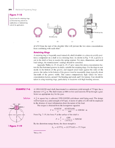
Figure 7–18
Typical uses for retaining rings.
(a) External ring and (b) its
application; (c) internal ring
and (d) its application.
Retaining ring
Retaining ring
(a) (b) (c) (d)
of d/10 from the start of the shoulder fillet will prevent the two stress concentrations
from combining with each other. 9
Retaining Rings
A retaining ring is frequently used instead of a shaft shoulder or a sleeve to axially posi-
tion a component on a shaft or in a housing bore. As shown in Fig. 7–18, a groove is
cut in the shaft or bore to receive the spring retainer. For sizes, dimensions, and axial
load ratings, the manufacturers’ catalogs should be consulted.
Appendix Tables A–15–16 and A–15–17 give values for stress-concentration fac-
tors for flat-bottomed grooves in shafts, suitable for retaining rings. For the rings to seat
nicely in the bottom of the groove, and support axial loads against the sides of the
groove, the radius in the bottom of the groove must be reasonably sharp, typically about
one-tenth of the groove width. This causes comparatively high values for stress-
concentration factors, around 5 for bending and axial, and 3 for torsion. Care should be
taken in using retaining rings, particularly in locations with high bending stresses.
EXAMPLE 7–6 A UNS G10350 steel shaft, heat-treated to a minimum yield strength of 75 kpsi, has a
diameter of 1 7 in. The shaft rotates at 600 rev/min and transmits 40 hp through a gear.
16
Select an appropriate key for the gear.
3
Solution A -in square key is selected, UNS G10200 cold-drawn steel being used. The design
8
will be based on a yield strength of 65 kpsi. A factor of safety of 2.80 will be employed
in the absence of exact information about the nature of the load.
t
a The torque is obtained from the horsepower equation
F
F 63 025H (63 025)(40)
T = = = 4200 lbf · in
b n 600
From Fig. 7–19, the force F at the surface of the shaft is
r
T 4200
F = = = 5850 lbf
r 1.4375/2
By the distortion-energy theory, the shear strength is
Figure 7–19
S sy = 0.577S y = (0.577)(65) = 37.5 kpsi
9 Ibid, p. 381.