
Page 422 - Shigley's Mechanical Engineering Design
P. 422
bud29281_ch07_358-408.qxd 12/8/09 12:52PM Page 397 ntt 203:MHDQ196:bud29281:0073529281:bud29281_pagefiles:
Shafts and Shaft Components 397
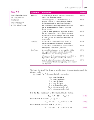
Table 7–9 Type of Fit Description Symbol
Descriptions of Preferred Clearance Loose running fit: for wide commercial tolerances or H11/c11
Fits Using the Basic allowances on external members
Hole System Free running fit: not for use where accuracy is H9/d9
essential, but good for large temperature variations,
Source: Preferred Metric
Limits and Fits, ANSI high running speeds, or heavy journal pressures
B4.2-1978. See also BS 4500. Close running fit: for running on accurate machines H8/f7
and for accurate location at moderate speeds and
journal pressures
Sliding fit: where parts are not intended to run freely, H7/g6
but must move and turn freely and locate accurately
Locational clearance fit: provides snug fit for location H7/h6
of stationary parts, but can be freely assembled and
disassembled
Transition Locational transition fit: for accurate location, a H7/k6
compromise between clearance and interference
Locational transition fit: for more accurate location H7/n6
where greater interference is permissible
Interference Locational interference fit: for parts requiring rigidity H7/p6
and alignment with prime accuracy of location but
without special bore pressure requirements
Medium drive fit: for ordinary steel parts or shrink fits on H7/s6
light sections, the tightest fit usable with cast iron
Force fit: suitable for parts that can be highly stressed H7/u6
or for shrink fits where the heavy pressing forces required
are impractical
The lower deviation H (for holes) is zero. For these, the upper deviation equals the
tolerance grade.
As shown in Fig. 7–20, we use the following notation:
D = basic size of hole
d = basic size of shaft
δ u = upper deviation
δ l = lower deviation
δ F = fundamental deviation
D = tolerance grade for hole
d = tolerance grade for shaft
Note that these quantities are all deterministic. Thus, for the hole,
D max = D +
D D min = D (7–36)
For shafts with clearance fits c, d, f, g, and h,
d max = d + δ F d min = d + δ F −
d (7–37)
For shafts with interference fits k, n, p, s, and u,
d min = d + δ F d max = d + δ F +
d (7–38)