
Page 426 - Shigley's Mechanical Engineering Design
P. 426
bud29281_ch07_358-408.qxd 12/8/09 12:52PM Page 401 ntt 203:MHDQ196:bud29281:0073529281:bud29281_pagefiles:
Shafts and Shaft Components 401
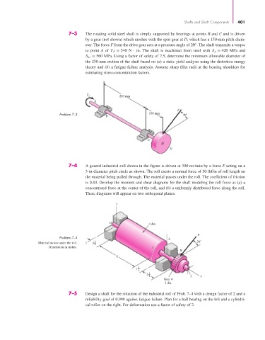
7–3 The rotating solid steel shaft is simply supported by bearings at points B and C and is driven
by a gear (not shown) which meshes with the spur gear at D, which has a 150-mm pitch diam-
eter. The force F from the drive gear acts at a pressure angle of 20°. The shaft transmits a torque
to point A of T A = 340 N · m. The shaft is machined from steel with S y = 420 MPa and
S ut = 560 MPa. Using a factor of safety of 2.5, determine the minimum allowable diameter of
the 250-mm section of the shaft based on (a) a static yield analysis using the distortion energy
theory and (b) a fatigue-failure analysis. Assume sharp fillet radii at the bearing shoulders for
estimating stress-concentration factors.
T A 250 mm
A
F
Problem 7–3 100 mm 20
B
C
D
7–4 A geared industrial roll shown in the figure is driven at 300 rev/min by a force F acting on a
3-in-diameter pitch circle as shown. The roll exerts a normal force of 30 lbf/in of roll length on
the material being pulled through. The material passes under the roll. The coefficient of friction
is 0.40. Develop the moment and shear diagrams for the shaft modeling the roll force as (a) a
concentrated force at the center of the roll, and (b) a uniformly distributed force along the roll.
These diagrams will appear on two orthogonal planes.
y
O 4 dia.
F
Problem 7–4 A
3 20°
Material moves under the roll. z 1
4
Dimensions in inches. 3
B
8
3
1
4
3
2
4 2 x
Gear 4
3 dia.
7–5 Design a shaft for the situation of the industrial roll of Prob. 7–4 with a design factor of 2 and a
reliability goal of 0.999 against fatigue failure. Plan for a ball bearing on the left and a cylindri-
cal roller on the right. For deformation use a factor of safety of 2.