Page 430 - Shigley's Mechanical Engineering Design
P. 430

bud29281_ch07_358-408.qxd  12/8/09  12:52PM  Page 405 ntt 203:MHDQ196:bud29281:0073529281:bud29281_pagefiles:


                                                                                          Shafts and Shaft Components  405
                                               steel. At steady-state speed, the gear transmits a radial load of 230 lbf and a tangential load of
                                               633 lbf at a pitch diameter of 8 in.
                                               (a) Determine fatigue factors of safety at any potentially critical locations.
                                               (b) Check that deflections satisfy the suggested minimums for bearings and gears.
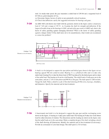
                                      7–24     An AISI 1020 cold-drawn steel shaft with the geometry shown in the figure carries a transverse
                                               load of 7 kN and a torque of 107 N · m. Examine the shaft for strength and deflection. If the
                                               largest allowable slope at the bearings is 0.001 rad and at the gear mesh is 0.0005 rad, what is the
                                               factor of safety guarding against damaging distortion? What is the factor of safety guarding
                                               against a fatigue failure? If the shaft turns out to be unsatisfactory, what would you recommend
                                               to correct the problem?


                                                                      7 kN
                                                           155
                                                                 55
                                                            40            45          40
                                                  30  35                                     35  30
                                                                                                     20
                                   Problem 7–24
                            Dimensions in millimeters.
                                                  30                                                 30
                                                   55                                              60
                                                        115          10                          85
                                                                                            150
                                                                           375
                                                All fillets 2 mm


                                      7–25     A shaft is to be designed to support the spur pinion and helical gear shown in the figure on two
                                               bearings spaced 700 mm center-to-center. Bearing A is a cylindrical roller and is to take only
                                               radial load; bearing B is to take the thrust load of 900 N produced by the helical gear and its share
                                               of the radial load. The bearing at B can be a ball bearing. The radial loads of both gears are in the
                                               same plane, and are 2.7 kN for the pinion and 900 N for the gear. The shaft speed is 1200 rev/min.
                                               Design the shaft. Make a sketch to scale of the shaft showing all fillet sizes, keyways, shoulders,
                                               and diameters. Specify the material and its heat treatment.


                                                  C brg                         C brg
                                                                                L
                                                  L
                                                                          50
                                                         100
                                   Problem 7–25
                            Dimensions in millimeters.
                                                 A                               B

                                                     175          400        125


                                      7–26     A heat-treated steel shaft is to be designed to support the spur gear and the overhanging worm
                                               shown in the figure. A bearing at A takes pure radial load. The bearing at B takes the worm-thrust
                                               load for either direction of rotation. The dimensions and the loading are shown in the figure; note
                                               that the radial loads are in the same plane. Make a complete design of the shaft, including a sketch
                                               of the shaft showing all dimensions. Identify the material and its heat treatment (if necessary).
                                               Provide an assessment of your final design. The shaft speed is 310 rev/min.
   425   426   427   428   429   430   431   432   433   434   435