
Page 428 - Shigley's Mechanical Engineering Design
P. 428
bud29281_ch07_358-408.qxd 12/8/09 12:52PM Page 403 ntt 203:MHDQ196:bud29281:0073529281:bud29281_pagefiles:
Shafts and Shaft Components 403
(d) Determine critical diameters of the shaft based on fatigue and static stresses at the critical
locations.
(e) Make any other dimensional decisions necessary to specify all diameters and axial dimen-
sions. Sketch the shaft to scale, showing all proposed dimensions.
(f) Check the deflection at the gear, and the slopes at the gear and the bearings for satisfaction of
the recommended limits in Table 7–2.
(g) If any of the deflections exceed the recommended limits, make appropriate changes to bring
them all within the limits.
3 8
24
E F
c
Problem 7–17
16
Dimensions in inches. 20
4 C D
b
8
A B
a
12 9 2 6
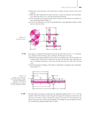
7–18 In the figure is a proposed shaft design to be used for the input shaft a in Prob. 7–17. A ball bear-
ing is planned for the left bearing, and a cylindrical roller bearing for the right.
(a) Determine the minimum fatigue factor of safety by evaluating at any critical locations. Use
a fatigue failure criteria that is considered to be typical of the failure data, rather than one
that is considered conservative. Also ensure that the shaft does not yield in the first load
cycle.
(b) Check the design for adequacy with respect to deformation, according to the recommenda-
tions in Table 7–2.
8
3
7 4
Problem 7–18 0.354 0.453
Shoulder fillets at bearing seat 1.875 1.875
1
0.030-in radius, others -in radius, 1.574 1.574 1.500
8
except right-hand bearing seat
transition, 1 in. The material
4
is 1030 HR. Keyways 3 in wide by
8
3 in deep. Dimensions in inches.
16
9
11 6
7–19* The shaft shown in the figure is proposed for the application defined in Prob. 3–72, p. 138. The
material is AISI 1018 cold-drawn steel. The gears seat against the shoulders, and have hubs with
setscrews to lock them in place. The effective centers of the gears for force transmission are
shown. The keyseats are cut with standard endmills. The bearings are press-fit against the shoul-
ders. Determine the minimum fatigue factor of safety.