
Page 427 - Shigley's Mechanical Engineering Design
P. 427
bud29281_ch07_358-408.qxd 12/9/09 5:19PM Page 402 ntt G4 Mac OS 9.2:Desktop Folder:MHDQ196/Budynas:
402 Mechanical Engineering Design
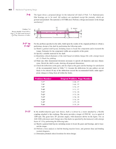
7–6 The figure shows a proposed design for the industrial roll shaft of Prob. 7–4. Hydrodynamic
film bearings are to be used. All surfaces are machined except the journals, which are
ground and polished. The material is 1035 HR steel. Perform a design assessment. Is the design
satisfactory?
1 1 4 1 1 keyway
Problem 7–6 4
O A
Bearing shoulder fillets 0.030 in,
1 1
others 16 in. Sled-runner keyway is
1
3 in long. Dimensions in inches.
2 7
1 1 10 1 1 4 8
2 2
7–7* to For the problem specified in the table, build upon the results of the original problem to obtain a
7–16* preliminary design of the shaft by performing the following tasks.
(a) Sketch a general shaft layout, including means to locate the components and to transmit the
torque. Estimates for the component widths are acceptable at this point.
(b) Specify a suitable material for the shaft.
(c) Determine critical diameters of the shaft based on infinite fatigue life with a design factor
of 1.5. Check for yielding.
(d) Make any other dimensional decisions necessary to specify all diameters and axial dimen-
sions. Sketch the shaft to scale, showing all proposed dimensions.
(e) Check the deflections at the gears, and the slopes at the gears and the bearings for satisfaction
of the recommended limits in Table 7–2. Assume the deflections for any pulleys are not
likely to be critical. If any of the deflections exceed the recommended limits, make appro-
priate changes to bring them all within the limits.
Problem Number Original Problem, Page Number
7–7* 3–68, 137
7–8* 3–69, 137
7–9* 3–70, 137
7–10* 3–71, 137
7–11* 3–72, 138
7–12* 3–73, 138
7–13* 3–74, 138
7–14* 3–76, 139
7–15* 3–77, 139
7–16* 3–79, 139
7–17 In the double-reduction gear train shown, shaft a is driven by a motor attached by a flexible
coupling attached to the overhang. The motor provides a torque of 2500 lbf · in at a speed of
1200 rpm. The gears have 20° pressure angles, with diameters shown on the figure. Use an
AISI 1020 cold-drawn steel. Design one of the shafts (as specified by the instructor) with a design
factor of 1.5 by performing the following tasks.
(a) Sketch a general shaft layout, including means to locate the gears and bearings, and to trans-
mit the torque.
(b) Perform a force analysis to find the bearing reaction forces, and generate shear and bending
moment diagrams.
(c) Determine potential critical locations for stress design.