
Page 425 - Shigley's Mechanical Engineering Design
P. 425
bud29281_ch07_358-408.qxd 12/9/09 4:29PM Page 400 ntt 203:MHDQ196:bud29281:0073529281:bud29281_pagefiles:
400 Mechanical Engineering Design
the steady compressive stresses due to the press fit. There is, however, a stress concen-
tration effect in the shaft bending stress near the ends of the hub, due to the sudden change
from compressed to uncompressed material. The design of the hub geometry, and there-
fore its uniformity and rigidity, can have a significant effect on the specific value of the
stress-concentration factor, making it difficult to report generalized values. For first esti-
mates, values are typically not greater than 2.
The amount of torque that can be transmitted through an interference fit can be esti-
mated with a simple friction analysis at the interface. The friction force is the product
of the coefficient of friction f and the normal force acting at the interface. The normal
force can be represented by the product of the pressure p and the surface area A of inter-
face. Therefore, the friction force F f is
F f = fN = f (pA) = f [p2π(d/2)l] = π fpld (7–48)
where l is the length of the hub. This friction force is acting with a moment arm of d/2
to provide the torque capacity of the joint, so
T = F f d/2 = π fpld(d/2)
T = (π/2) fpld 2 (7–49)
The minimum interference, from Eq. (7–42), should be used to determine the min-
imum pressure to check for the maximum amount of torque that the joint should be
designed to transmit without slipping.
PROBLEMS
Problems marked with an asterisk (*) are linked to problems in other chapters, as summarized in
Table 1–1 of Sec. 1–16, p. 24.
7–1 A shaft is loaded in bending and torsion such that M a = 70 N · m, T a = 45 N · m, M m =
55 N · m, and T m = 35 N · m. For the shaft, S u = 700 MPa and S y = 560 MPa, and a fully cor-
rected endurance limit of S e = 210 MPa is assumed. Let K f = 2.2 and K fs = 1.8. With a design
factor of 2.0 determine the minimum acceptable diameter of the shaft using the
(a) DE-Gerber criterion.
(b) DE-elliptic criterion.
(c) DE-Soderberg criterion.
(d) DE-Goodman criterion.
Discuss and compare the results.
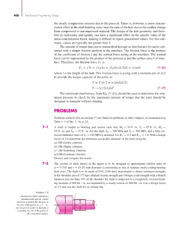
7–2 The section of shaft shown in the figure is to be designed to approximate relative sizes of
d = 0.75D and r = D/20 with diameter d conforming to that of standard metric rolling-bearing
bore sizes. The shaft is to be made of SAE 2340 steel, heat-treated to obtain minimum strengths
in the shoulder area of 175 kpsi ultimate tensile strength and 160 kpsi yield strength with a Brinell
hardness not less than 370. At the shoulder the shaft is subjected to a completely reversed bend-
ing moment of 600 lbf · in, accompanied by a steady torsion of 400 lbf · in. Use a design factor
of 2.5 and size the shaft for an infinite life.
Problem 7–2
r
Section of a shaft containing a
grinding-relief groove. Unless
otherwise specified, the diameter at
the root of the groove d r = d − 2r, D d
and though the section of diameter d
is ground, the root of the groove is
still a machined surface.