
Page 429 - Shigley's Mechanical Engineering Design
P. 429
bud29281_ch07_358-408.qxd 12/8/09 12:52PM Page 404 ntt 203:MHDQ196:bud29281:0073529281:bud29281_pagefiles:
404 Mechanical Engineering Design
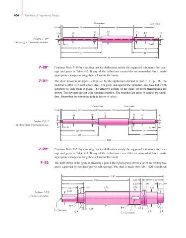
Gear center Gear center
0.5 16 14 9
2.5
1.00 1.3 1.75 1.75 1.3 1.00
Problem 7–19*
All fillets 1 in. Dimensions in inches.
16
1 2
15 10
17 11
41
7–20* Continue Prob. 7–19 by checking that the deflections satisfy the suggested minimums for bear-
ings and gears in Table 7–2. If any of the deflections exceed the recommended limits, make
appropriate changes to bring them all within the limits.
7–21* The shaft shown in the figure is proposed for the application defined in Prob. 3–73, p. 138. The
material is AISI 1018 cold-drawn steel. The gears seat against the shoulders, and have hubs with
setscrews to lock them in place. The effective centers of the gears for force transmission are
shown. The keyseats are cut with standard endmills. The bearings are press-fit against the shoul-
ders. Determine the minimum fatigue factor of safety.
Gear center Gear center
15 400 350 300
75
50 50 42
30 40 30
Problem 7–21*
All fillets 2 mm. Dimensions in mm.
30 30
385 285
425 325
1080
7–22* Continue Prob. 7–21 by checking that the deflections satisfy the suggested minimums for bear-
ings and gears in Table 7–2. If any of the deflections exceed the recommended limits, make
appropriate changes to bring them all within the limits.
7–23 The shaft shown in the figure is driven by a gear at the right keyway, drives a fan at the left keyway,
and is supported by two deep-groove ball bearings. The shaft is made from AISI 1020 cold-drawn
12.87
8.50 0.20 2.20
2.75 0.485 0.75
2.0 1.181 1.70 1.750 1.40
1.181
Problem 7–23 1.000
Dimensions in inches. 2.0
1
16 R. 1 R.
1 × 1 keyway 0.15 8 0.1 R. 1 1
4 8 1 R. 3 3 R. R.
32 × keyway 8 32
8 16