
Page 417 - Shigley's Mechanical Engineering Design
P. 417
bud29281_ch07_358-408.qxd 12/9/09 4:35PM Page 392 ntt 203:MHDQ196:bud29281:0073529281:bud29281_pagefiles:
392 Mechanical Engineering Design
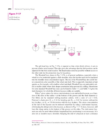
Figure 7–17
(a) Gib-head key;
(b) Woodruff key.
1
Taper in over 12 in
8
w w
h
(a)
D
w
(b)
The gib-head key, in Fig. 7–17a, is tapered so that, when firmly driven, it acts to
prevent relative axial motion. This also gives the advantage that the hub position can be
adjusted for the best axial location. The head makes removal possible without access to
the other end, but the projection may be hazardous.
The Woodruff key, shown in Fig. 7–17b, is of general usefulness, especially when a
wheel is to be positioned against a shaft shoulder, since the keyslot need not be machined
into the shoulder stress concentration region. The use of the Woodruff key also yields bet-
ter concentricity after assembly of the wheel and shaft. This is especially important at high
speeds, as, for example, with a turbine wheel and shaft. Woodruff keys are particularly use-
ful in smaller shafts where their deeper penetration helps prevent key rolling. Dimensions
for some standard Woodruff key sizes can be found in Table 7–7, and Table 7–8 gives the
shaft diameters for which the different keyseat widths are suitable.
8
Pilkey gives values for stress concentrations in an end-milled keyseat, as a func-
tion of the ratio of the radius r at the bottom of the groove and the shaft diameter d.
For fillets cut by standard milling-machine cutters, with a ratio of r/d = 0.02,
Peterson’s charts give K t = 2.14 for bending and K ts = 2.62 for torsion without the
key in place, or K ts = 3.0 for torsion with the key in place. The stress concentration
at the end of the keyseat can be reduced somewhat by using a sled-runner keyseat,
eliminating the abrupt end to the keyseat, as shown in Fig. 7–17. It does, however, still
have the sharp radius in the bottom of the groove on the sides. The sled-runner key-
seat can only be used when definite longitudinal key positioning is not necessary. It is
also not as suitable near a shoulder. Keeping the end of a keyseat at least a distance
8 W. D. Pilkey, Peterson’s Stress-Concentration Factors, 2nd ed., John Wiley & Sons, New York, 1997,
pp. 408–409.