
Page 408 - Shigley's Mechanical Engineering Design
P. 408
bud29281_ch07_358-408.qxd 12/8/09 12:52PM Page 383 ntt 203:MHDQ196:bud29281:0073529281:bud29281_pagefiles:
Shafts and Shaft Components 383
If torsional stiffness is defined as k i = T i /θ i and, since θ i = T i /k i and
% % %
θ = θ i = (T i /k i ), for constant torque θ = T (1/k i ), it follows that the torsional
stiffness of the shaft k in terms of segment stiffnesses is
1 $ 1
= (7–21)
k k i
7–6 Critical Speeds for Shafts
When a shaft is turning, eccentricity causes a centrifugal force deflection, which is
resisted by the shaft’s flexural rigidity EI. As long as deflections are small, no harm is
done. Another potential problem, however, is called critical speeds: at certain speeds
the shaft is unstable, with deflections increasing without upper bound. It is fortunate
that although the dynamic deflection shape is unknown, using a static deflection curve
gives an excellent estimate of the lowest critical speed. Such a curve meets the bound-
ary condition of the differential equation (zero moment and deflection at both bearings)
and the shaft energy is not particularly sensitive to the exact shape of the deflection
curve. Designers seek first critical speeds at least twice the operating speed.
The shaft, because of its own mass, has a critical speed. The ensemble of attach-
ments to a shaft likewise has a critical speed that is much lower than the shaft’s intrin-
sic critical speed. Estimating these critical speeds (and harmonics) is a task of the
designer. When geometry is simple, as in a shaft of uniform diameter, simply supported,
4
the task is easy. It can be expressed as
'
2
& 2
π EI π gE I
ω 1 = = (7–22)
l m l Aγ
where m is the mass per unit length, A the cross-sectional area, and γ the specific
weight. For an ensemble of attachments, Rayleigh’s method for lumped masses gives 5
' %
g w i y i
ω 1 = % 2 (7–23)
w i y
i
where w i is the weight of the ith location and y i is the deflection at the ith body location.
It is possible to use Eq. (7–23) for the case of Eq. (7–22) by partitioning the shaft into
segments and placing its weight force at the segment centroid as seen in Fig. 7–12.
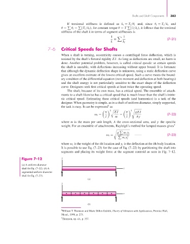
Figure 7–12 y
(a) A uniform-diameter
shaft for Eq. (7–22). (b) A x
segmented uniform-diameter
shaft for Eq. (7–23).
(a)
y
x
(b)
4 William T. Thomson and Marie Dillon Dahleh, Theory of Vibration with Applications, Prentice Hall,
5th ed., 1998, p. 273.
5 Thomson, op. cit., p. 357.