
Page 400 - Shigley's Mechanical Engineering Design
P. 400
bud29281_ch07_358-408.qxd 12/18/09 7:31 PM Page 375 epg Disk1:Desktop Folder:TEMPWORK:Don't-Delete Jobs:MHDQ196/Budynas:
Shafts and Shaft Components 375
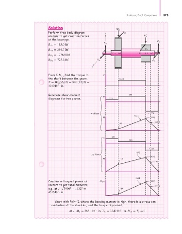
Solution
W 23 r
Perform free body diagram y W 23 t
r
analysis to get reaction forces W 54
at the bearings.
R By
R
R Az = 115.0 lbf Ay
t
W
R Ay = 356.7 lbf A 54 B
x G I J K
R Bz = 1776.0 lbf
R By = 725.3 lbf R Az R Bz
z
From M x , find the torque in T
the shaft between the gears, 3240
t
T = W (d 3 /2) = 540 (12/2) =
23
3240 lbf · in .
Generate shear-moment 655
V
diagrams for two planes. 115
x-z Plane 1776
3341
M 3996
2220
230
357
V
160
725
1472
x-y Plane
1632
M 713
907
3651
Combine orthogonal planes as M TOT 4316
vectors to get total moments,
√ 2398
2
2
e.g., at J, 3996 + 1632 = 749
4316 lbf · in.
Start with Point I, where the bending moment is high, there is a stress con-
centration at the shoulder, and the torque is present.
At I, M a = 3651 lbf in, T m = 3240 lbf in, M m = T a = 0