
Page 389 - Shigley's Mechanical Engineering Design
P. 389
bud29281_ch07_358-408.qxd 12/8/09 12:52PM Page 364 ntt 203:MHDQ196:bud29281:0073529281:bud29281_pagefiles:
364 Mechanical Engineering Design
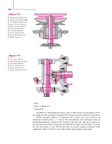
Figure 7–3
Tapered roller bearings used
in a mowing machine spindle.
This design represents good
practice for the situation in
which one or more torque-
transfer elements must
be mounted outboard.
(Source: Redrawn from
material furnished by The
Timken Company.)
Figure 7–4
A bevel-gear drive in
which both pinion and gear
are straddle-mounted.
(Source: Redrawn from
material furnished by
Gleason Machine Division.)
• Pins
• Press or shrink fits
• Tapered fits
In addition to transmitting the torque, many of these devices are designed to fail if
the torque exceeds acceptable operating limits, protecting more expensive components.
Details regarding hardware components such as keys, pins, and setscrews are
addressed in detail in Sec. 7–7. One of the most effective and economical means of
transmitting moderate to high levels of torque is through a key that fits in a groove in
the shaft and gear. Keyed components generally have a slip fit onto the shaft, so assem-
bly and disassembly is easy. The key provides for positive angular orientation of the
component, which is useful in cases where phase angle timing is important.