
Page 544 - Shigley's Mechanical Engineering Design
P. 544
bud29281_ch10_517-568.qxd 12/16/2009 7:14 pm Page 518 pinnacle 203:MHDQ196:bud29281:0073529281:bud29281_pagefiles:
518 Mechanical Engineering Design
When a designer wants rigidity, negligible deflection is an acceptable approximation
as long as it does not compromise function. Flexibility is sometimes needed and is
often provided by metal bodies with cleverly controlled geometry. These bodies can
exhibit flexibility to the degree the designer seeks. Such flexibility can be linear or
nonlinear in relating deflection to load. These devices allow controlled application of
force or torque; the storing and release of energy can be another purpose. Flexibility
allows temporary distortion for access and the immediate restoration of function.
Because of machinery’s value to designers, springs have been intensively studied;
moreover, they are mass-produced (and therefore low cost), and ingenious configura-
tions have been found for a variety of desired applications. In this chapter we will
discuss the more frequently used types of springs, their necessary parametric rela-
tionships, and their design.
In general, springs may be classified as wire springs, flat springs, or special-
shaped springs, and there are variations within these divisions. Wire springs include
helical springs of round or square wire, made to resist and deflect under tensile, com-
pressive, or torsional loads. Flat springs include cantilever and elliptical types, wound
motor- or clock-type power springs, and flat spring washers, usually called Belleville
springs.
10–1 Stresses in Helical Springs
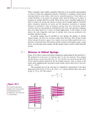
Figure 10–1a shows a round-wire helical compression spring loaded by the axial force F.
We designate D as the mean coil diameter and d as the wire diameter. Now imagine
that the spring is cut at some point (Fig. 10–1b), a portion of it removed, and the effect
of the removed portion replaced by the net internal reactions. Then, as shown in the
figure, from equilibrium the cut portion would contain a direct shear force F and a tor-
sion T = FD/2.
The maximum stress in the wire may be computed by superposition of the direct
shear stress given by Eq. (3–23), p. 89, with V = F and the torsional shear stress given
by Eq. (3–37), p. 101. The result is
Tr F
τ max = + (a)
J A
Figure 10–1 F F
(a) Axially loaded helical
spring; (b) free-body diagram
showing that the wire is
subjected to a direct shear and
a torsional shear.
d T = FD 2
F
(b)
F
D
(a)