
Page 548 - Shigley's Mechanical Engineering Design
P. 548
bud29281_ch10_517-568.qxd 12/16/2009 7:14 pm Page 522 pinnacle 203:MHDQ196:bud29281:0073529281:bud29281_pagefiles:
522 Mechanical Engineering Design
10–5 Stability
In Chap. 4 we learned that a column will buckle when the load becomes too large.
Similarly, compression coil springs may buckle when the deflection becomes too
large. The critical deflection is given by the equation
1/2
C 2
y cr = L 0 C 1 1 − 1 − 2 (10–10)
λ eff
5
where y cr is the deflection corresponding to the onset of instability. Samónov states that
7
6
this equation is cited by Wahl and verified experimentally by Haringx. The quantity
λ eff in Eq. (10–10) is the effective slenderness ratio and is given by the equation
αL 0
λ eff = (10–11)
D
C and C are elastic constants defined by the equations
2
1
E
C =
1
2(E − G)
2
2π (E − G)
C =
2
2G + E
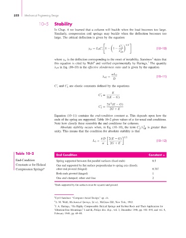
Equation (10–11) contains the end-condition constant α. This depends upon how the
ends of the spring are supported. Table 10–2 gives values of α for usual end conditions.
Note how closely these resemble the end conditions for columns.
Absolute stability occurs when, in Eq. (10–10), the term C /λ 2 eff is greater than
2
unity. This means that the condition for absolute stability is that
1/2
π D 2(E − G)
L 0 < (10–12)
α 2G + E
Table 10–2
End Condition Constant
End-Condition Spring supported between flat parallel surfaces (fixed ends) 0.5
Constants α for Helical One end supported by flat surface perpendicular to spring axis (fixed);
Compression Springs* other end pivoted (hinged) 0.707
Both ends pivoted (hinged) 1
One end clamped; other end free 2
Ends supported by flat surfaces must be squared and ground.
∗
5 Cyril Samónov “Computer-Aided Design,” op. cit.
6 A. M. Wahl, Mechanical Springs, 2d ed., McGraw-Hill, New York, 1963.
7 J. A. Haringx, “On Highly Compressible Helical Springs and Rubber Rods and Their Application for
Vibration-Free Mountings,” I and II, Philips Res. Rep., vol. 3, December 1948, pp. 401–449, and vol. 4,
February 1949, pp. 49–80.