
Page 140 -
P. 140
5.1 Context models 123
Confirm
Detention [Not Available] Transfer to
Decision Police Station
Find Secure
Place [Available] Inform
Transfer to Social Care
Inform Secure
Patient of [Dangerous] Hospital
Rights Inform Next
of Kin
Record
Detention Admit to Update
Decision [Not Hospital Register
Dangerous]
«system» «system» «system»
MHC-PMS Admissions MHC-PMS
System
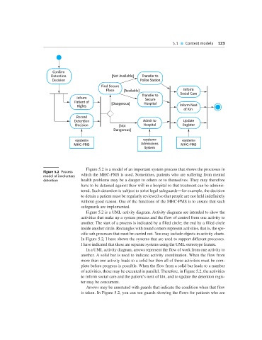
Figure 5.2 is a model of an important system process that shows the processes in
Figure 5.2 Process
model of involuntary which the MHC-PMS is used. Sometimes, patients who are suffering from mental
detention health problems may be a danger to others or to themselves. They may therefore
have to be detained against their will in a hospital so that treatment can be adminis-
tered. Such detention is subject to strict legal safeguards—for example, the decision
to detain a patient must be regularly reviewed so that people are not held indefinitely
without good reason. One of the functions of the MHC-PMS is to ensure that such
safeguards are implemented.
Figure 5.2 is a UML activity diagram. Activity diagrams are intended to show the
activities that make up a system process and the flow of control from one activity to
another. The start of a process is indicated by a filled circle; the end by a filled circle
inside another circle. Rectangles with round corners represent activities, that is, the spe-
cific sub-processes that must be carried out. You may include objects in activity charts.
In Figure 5.2, I have shown the systems that are used to support different processes.
I have indicated that these are separate systems using the UML stereotype feature.
In a UML activity diagram, arrows represent the flow of work from one activity to
another. A solid bar is used to indicate activity coordination. When the flow from
more than one activity leads to a solid bar then all of these activities must be com-
plete before progress is possible. When the flow from a solid bar leads to a number
of activities, these may be executed in parallel. Therefore, in Figure 5.2, the activities
to inform social care and the patient’s next of kin, and to update the detention regis-
ter may be concurrent.
Arrows may be annotated with guards that indicate the condition when that flow
is taken. In Figure 5.2, you can see guards showing the flows for patients who are