
Page 142 -
P. 142
5.2 Interaction models 125
Transfer Data
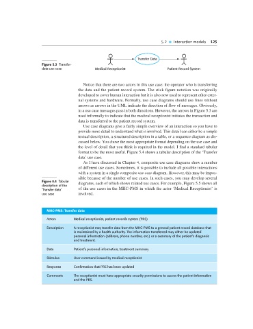
Figure 5.3 Transfer-
data use case Medical Receptionist Patient Record System
Notice that there are two actors in this use case: the operator who is transferring
the data and the patient record system. The stick figure notation was originally
developed to cover human interaction but it is also now used to represent other exter-
nal systems and hardware. Formally, use case diagrams should use lines without
arrows as arrows in the UML indicate the direction of flow of messages. Obviously,
in a use case messages pass in both directions. However, the arrows in Figure 5.3 are
used informally to indicate that the medical receptionist initiates the transaction and
data is transferred to the patient record system.
Use case diagrams give a fairly simple overview of an interaction so you have to
provide more detail to understand what is involved. This detail can either be a simple
textual description, a structured description in a table, or a sequence diagram as dis-
cussed below. You chose the most appropriate format depending on the use case and
the level of detail that you think is required in the model. I find a standard tabular
format to be the most useful. Figure 5.4 shows a tabular description of the ‘Transfer
data’ use case.
As I have discussed in Chapter 4, composite use case diagrams show a number
of different use cases. Sometimes, it is possible to include all possible interactions
with a system in a single composite use case diagram. However, this may be impos-
sible because of the number of use cases. In such cases, you may develop several
Figure 5.4 Tabular diagrams, each of which shows related use cases. For example, Figure 5.5 shows all
description of the
‘Transfer data’ of the use cases in the MHC-PMS in which the actor ‘Medical Receptionist’ is
use case involved.
MHC-PMS: Transfer data
Actors Medical receptionist, patient records system (PRS)
Description A receptionist may transfer data from the MHC-PMS to a general patient record database that
is maintained by a health authority. The information transferred may either be updated
personal information (address, phone number, etc.) or a summary of the patient’s diagnosis
and treatment.
Data Patient’s personal information, treatment summary
Stimulus User command issued by medical receptionist
Response Confirmation that PRS has been updated
Comments The receptionist must have appropriate security permissions to access the patient information
and the PRS.