
Page 143 -
P. 143
126 Chapter 5 System modeling
Register
Patient
Unregister
Patient
View Patient
Info.
Medical
Receptionist
Transfer Data
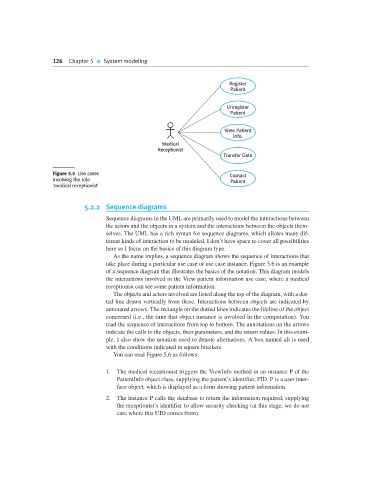
Figure 5.5 Use cases Contact
involving the role Patient
‘medical receptionist’
5.2.2 Sequence diagrams
Sequence diagrams in the UML are primarily used to model the interactions between
the actors and the objects in a system and the interactions between the objects them-
selves. The UML has a rich syntax for sequence diagrams, which allows many dif-
ferent kinds of interaction to be modeled. I don’t have space to cover all possibilities
here so I focus on the basics of this diagram type.
As the name implies, a sequence diagram shows the sequence of interactions that
take place during a particular use case or use case instance. Figure 5.6 is an example
of a sequence diagram that illustrates the basics of the notation. This diagram models
the interactions involved in the View patient information use case, where a medical
receptionist can see some patient information.
The objects and actors involved are listed along the top of the diagram, with a dot-
ted line drawn vertically from these. Interactions between objects are indicated by
annotated arrows. The rectangle on the dotted lines indicates the lifeline of the object
concerned (i.e., the time that object instance is involved in the computation). You
read the sequence of interactions from top to bottom. The annotations on the arrows
indicate the calls to the objects, their parameters, and the return values. In this exam-
ple, I also show the notation used to denote alternatives. A box named alt is used
with the conditions indicated in square brackets.
You can read Figure 5.6 as follows:
1. The medical receptionist triggers the ViewInfo method in an instance P of the
PatientInfo object class, supplying the patient’s identifier, PID. P is a user inter-
face object, which is displayed as a form showing patient information.
2. The instance P calls the database to return the information required, supplying
the receptionist’s identifier to allow security checking (at this stage, we do not
care where this UID comes from).