
Page 291 -
P. 291
262 PART THREE CONVENTIONAL METHODS FOR SOFTWARE ENGINEERING
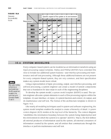
FIGURE 10.4
Generic Specific aspect of the system or its environment
traceability
table A01 A02 A03 A04 A05 Aii
Requirement
R01
R02
R03
R04
R05
Rnn
10.6 SYSTEM MODELING
Every computer-based system can be modeled as an information transform using an
input-processing-output template. Hatley and Pirbhai [HAT87] have extended this
view to include two additional system features—user interface processing and main-
tenance and self-test processing. Although these additional features are not present
for every computer-based system, they are very common, and their specification
makes any system model more robust.
XRef
Using a representation of input, processing, output, user interface processing, and
Other system modeling
methods take an self-test processing, a system engineer can create a model of system components
object-oriented view. that sets a foundation for later steps in each of the engineering disciplines.
The UML approach can
be applied at the To develop the system model, a system model template [HAT87] is used. The sys-
system level and is tem engineer allocates system elements to each of five processing regions within the
discussed in Chapters template: (1) user interface, (2) input, (3) system function and control, (4) output, and
21 and 22.
(5) maintenance and self-test. The format of the architecture template is shown in
Figure 10.5.
Like nearly all modeling techniques used in system and software engineering, the
system model template enables the analyst to create a hierarchy of detail. A system
context diagram (SCD) resides at the top level of the hierarchy. The context diagram
"establishes the information boundary between the system being implemented and
the environment in which the system is to operate" [HAT87]. That is, the SCD defines
all external producers of information used by the system, all external consumers of
information created by the system, and all entities that communicate through the
interface or perform maintenance and self-test.