
Page 292 -
P. 292
CHAPTER 10 SYSTEM ENGINEERING 263
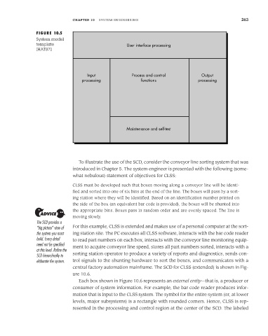
FIGURE 10.5
System model
template User interface processing
[HAT87]
Input Process and control Output
processing functions processing
Maintenance and self-test
To illustrate the use of the SCD, consider the conveyor line sorting system that was
introduced in Chapter 5. The system engineer is presented with the following (some-
what nebulous) statement of objectives for CLSS:
CLSS must be developed such that boxes moving along a conveyor line will be identi-
fied and sorted into one of six bins at the end of the line. The boxes will pass by a sort-
ing station where they will be identified. Based on an identification number printed on
the side of the box (an equivalent bar code is provided), the boxes will be shunted into
the appropriate bins. Boxes pass in random order and are evenly spaced. The line is
moving slowly.
The SCD provides a
“big picture” view of For this example, CLSS is extended and makes use of a personal computer at the sort-
the system you must ing station site. The PC executes all CLSS software, interacts with the bar code reader
build. Every detail to read part numbers on each box, interacts with the conveyor line monitoring equip-
need not be specified ment to acquire conveyor line speed, stores all part numbers sorted, interacts with a
at this level. Refine the
SCD hierarchically to sorting station operator to produce a variety of reports and diagnostics, sends con-
elaborate the system. trol signals to the shunting hardware to sort the boxes, and communicates with a
central factory automation mainframe. The SCD for CLSS (extended) is shown in Fig-
ure 10.6.
Each box shown in Figure 10.6 represents an external entity—that is, a producer or
consumer of system information. For example, the bar code reader produces infor-
mation that is input to the CLSS system. The symbol for the entire system (or, at lower
levels, major subsystems) is a rectangle with rounded corners. Hence, CLSS is rep-
resented in the processing and control region at the center of the SCD. The labeled