
Page 294 -
P. 294
CHAPTER 10 SYSTEM ENGINEERING 265
FIGURE 10.7 Operator
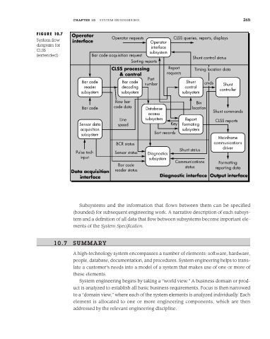
System flow interface Operator requests Operator CLSS queries, reports, displays
diagram for
interface
CLSS subsystem
(extended) Bar code acquisition request
Shunt control status
Sorting reports
CLSS processing Report Timing location data
& control requests
Part
Bar code Bar code number Shunt cmds Shunt
reader decoding control
subsystem subsystem subsystem controller
Raw bar Bin
Bar code code data Database location
access Shunt commands
Line subsystem Report CLSS reports
Sensor data speed Key formating
acquisition subsystem
subsystem Sort records
Mainframe
BCR status communications
driver
Shunt status
Pulse tach Sensor status Diagnostics
input subsystem
Communications Formatting
Bar code status reporting data
Data acquisition reader status
interface Diagnostic interface Output interface
Subsystems and the information that flows between them can be specified
(bounded) for subsequent engineering work. A narrative description of each subsys-
tem and a definition of all data that flow between subsystems become important ele-
ments of the System Specification.
10.7 SUMMARY
A high-technology system encompasses a number of elements: software, hardware,
people, database, documentation, and procedures. System engineering helps to trans-
late a customer’s needs into a model of a system that makes use of one or more of
these elements.
System engineering begins by taking a “world view.” A business domain or prod-
uct is analyzed to establish all basic business requirements. Focus is then narrowed
to a “domain view,” where each of the system elements is analyzed individually. Each
element is allocated to one or more engineering components, which are then
addressed by the relevant engineering discipline.