
Page 328 - Standard Handbook Petroleum Natural Gas Engineering VOLUME2
P. 328
Fluid Movement in Waterflooded Reservoirs 495
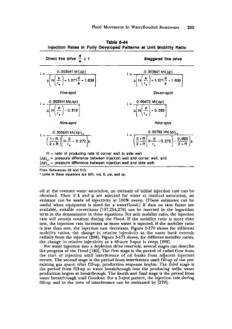
Table 5-44
lnjectlon Rates In Fully Developed Patterns at Unit Moblllty Ratio
~
d
Direct line drlve 2 1 Staggered line drive
i= 0.003541 kh(Ap) i= 0.003541 kh( Ap)
Five-spot Seven-spot
. 0.003541 kh(Ap)
I=
-
.[In( t) 0.6191
Nine-spot Nine-spot
. 0.003541 kh(Ap),, 0.00782 kh( Ap)i,s
I= (=I[ In; - 0. ,721, I= [In - 0.2721 - %)p 0693
. [
R = ratio of producing rate of corner well to side well
(AP);,~ = pressure difference between injection well and corner well, and
(Ap),,, = pressure difference between injection well and side well.
From References 25 and 313.
* Units in these equations are B/D, mid, A, psi, and cp.
oil at the connate water saturation, an estimate of initial injection rate can be
obtained. Then if k and p are selected for water at residual saturation, an
estimate can be made d injectivity at 100% sweep. (These estimates can be
useful when equipment is sized for a waterflood.) If data on skin factor are
available, suitable corrections [197,254,278] can be inserted in the logarithm
term in the denominator in these equations. For unit mobility ratio, the injection
rate will remain constant during the flood. If the mobility ratio is more than
one, the injection rate increases as more water is injected; if the mobility ratio
is less than one, the injection rate decreases. Figure 5-170 shows for different
mobility ratios, the change in relative injectivity as the water bank extends
radially from the injector [298]. Figure 5-171 shows, for different mobility ratios,
the change in relative injectivity as a 40-acre 5-spot is swept [298].
For water injection into a depletion drive reservoir, several stages can describe
the progress of the flood [180]. The first stage is the period of radial flow from
the start of injection until interference of oil banks from adjacent injectors
occurs. The second stage is the period from interference until fill-up of the pre-
existing gas space; after fill-up, production response begins. The third stage is
the period from fill-up to water breakthrough into the producing wells; water
production begins at breakthrough. The fourth and final stage is the period fbm
water breakthrough until floodout. For a 5-spot pattern, the injection rate during
fill-up and to the time of interference can be estimated by [278]: