
Page 117 - Steam Turbines Design, Applications, and Rerating
P. 117
98 Chapter Five
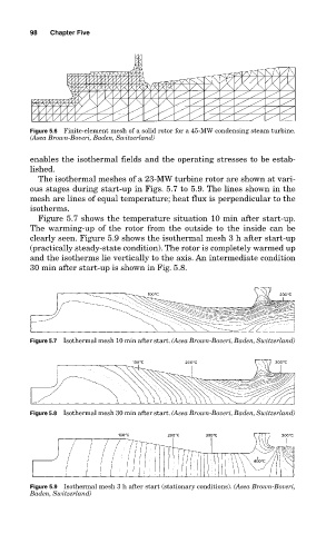
Figure 5.6 Finite-element mesh of a solid rotor for a 45-MW condensing steam turbine.
(Asea Brown-Boveri, Baden, Switzerland)
enables the isothermal fields and the operating stresses to be estab-
lished.
The isothermal meshes of a 23-MW turbine rotor are shown at vari-
ous stages during start-up in Figs. 5.7 to 5.9. The lines shown in the
mesh are lines of equal temperature; heat flux is perpendicular to the
isotherms.
Figure 5.7 shows the temperature situation 10 min after start-up.
The warming-up of the rotor from the outside to the inside can be
clearly seen. Figure 5.9 shows the isothermal mesh 3 h after start-up
(practically steady-state condition). The rotor is completely warmed up
and the isotherms lie vertically to the axis. An intermediate condition
30 min after start-up is shown in Fig. 5.8.
Figure 5.7 Isothermal mesh 10 min after start. (Asea Brown-Boveri, Baden, Switzerland)
Figure 5.8 Isothermal mesh 30 min after start. (Asea Brown-Boveri, Baden, Switzerland)
Figure 5.9 Isothermal mesh 3 h after start (stationary conditions). (Asea Brown-Boveri,
Baden, Switzerland)