
Page 120 - Steam Turbines Design, Applications, and Rerating
P. 120
Rotors for Reaction Turbines 101
Figure 5.12 Location of test pieces, (1) and (2), for
strength testing of solid rotors. (Asea Brown-
Boveri, Baden, Switzerland)
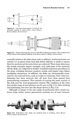
Figure 5.13 Section through the rotor of a 60-MW condensing turbine. This welded rotor
will be fitted with reaction blading. (Asea Brown-Boveri, Baden, Switzerland)
sonically tested at the steel plant, and, in addition, mechanical tests are
carried out on pieces from each disk before delivery is made to ensure
that the mechanical characteristics are achieved. These tests determine
the tensile strength, impact strength, and yield point of the material.
All the disks are subjected to further standard inspection procedures in
the shop, including chemical analysis, tensile and impact tests, before
machining commences. In addition, the disks are ultrasonically exam-
ined for any internal flaws, such as cracks or inclusions. Only when con-
firmation has been received that all tests have been passed does
premachining commence. This consists of turning the inner contour of
the disk and the weld preparation contour. The condition of the rotor
during this stage of manufacture can be seen in Fig. 5.14. After welding
and machining, the rotor has the shape shown in Fig. 5.15.
Although no longer in the size range of mechanical drive steam tur-
bines, large utility (power generation) turbines are of some interest.
Figure 5.14 Individual rotor disks are stacked prior to welding. (Asea Brown-
Boveri, Baden, Switzerland)