
Page 167 - Steam Turbines Design, Applications, and Rerating
P. 167
Governors and Control Systems 147
desirable to limit the maximum governor speed to 1200 r/min to elimi-
nate the need for a governor oil cooler. The governor drive arrangement
is generally applied in conjunction with turbine lube oil systems sup-
plying approximately 0.5 g/min (2 l/min) of oil for drive gear lubrication.
The Woodward PG governor (Fig. 8.6) is a mechanical oil relay gov-
ernor. The mechanical force developed by the governor weights is
transmitted by oil pressure to a power piston moving the governor
valve. The advantage of this system is that only a small amount of force
is required to move the pilot valve, as opposed to the large amount of
mechanical force necessary in a direct-acting system. Consequently,
smaller, more accurate elements may be used. Friction losses are thus
reduced to a minimum. The result is a better governor control. The gov-
ernor system is not truly isochronous because of governor valve(s)
unbalance and system friction. The speed is adjusted manually by
means of an external knob that is connected to the governor spring.
The speed is, therefore, varied by changing the spring tension, which
changes the force on the governor pilot. This governor is also available
with an electrical speed changer that uses an electric motor connected
to the governor spring.
The PG-PL governor includes an integral air speed changer; other-
wise, it is similar in operation to the standard PG governor. The air sig-
nal positions a secondary pilot valve. This pilot valve directs oil to the
speed-setting piston mounted on the speeder spring to change the ten-
sion of the speeder spring, similar to action on the hand speed changer
in the PG governor. With a given air signal applied, the governor speed
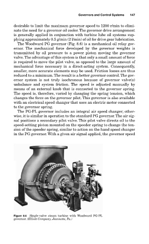
Figure 8.6 Single-valve steam turbine with Woodward PG-PL
governor. (Elliott Company, Jeannette, Pa.)