
Page 196 - Steam Turbines Design, Applications, and Rerating
P. 196
Rotor Dynamics Technology 175
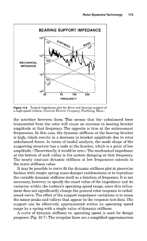
Figure 10.6 Typical impedance plot for drive end bearing support of
a high-speed turbine. (General Electric Company, Fitchburg, Mass.)
the interface between them. This means that the unbalanced force
transmitted from the rotor will cause an increase in bearing bracket
amplitude at that frequency. The opposite is true at the antiresonant
frequencies. In this case, the dynamic stiffness at the bearing bracket
is high, which results in a decrease in bracket amplitude due to rotor
unbalanced forces. In terms of modal analysis, the mode shape of the
supporting structure has a node at the bracket, which is a point of low
amplitude. (Theoretically, it would be zero.) The mechanical impedance
at the bottom of each valley is the system damping at that frequency.
The nearly constant dynamic stiffness at low frequencies extends to
the static stiffness value.
It may be possible to curve fit the dynamic stiffness plot in piecewise
fashion with simple spring-mass-damper combinations or to reproduce
the variable dynamic stiffness itself as a function of frequency. It is not
necessary, however, to specify the exact value of the impedance and its
variation within the turbine’s operating speed range, since this refine-
ment does not significantly change the general rotor response to unbal-
anced curve. The effect of the support impedance variations is to cause
the minor peaks and valleys that appear in the response test data. The
support can be effectively approximated within an operating speed
range by a spring with a single value of dynamic stiffness.
A curve of dynamic stiffness vs. operating speed is used for design
purposes (Fig. 10.7). The irregular lines are a simplified approximation