
Page 191 - Steam Turbines Design, Applications, and Rerating
P. 191
170 Chapter Ten
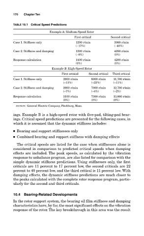
TABLE 10.1 Critical Speed Predictions
Example A: Medium-Speed Rotor
First critical Second critical
Case 1. Stiffness only 1200 r/min 3000 r/min
(−17%) (−40%)
Case 2. Stiffness and damping 1300 r/min 4200 r/min
(−8%) (0%)
Response calculation 1400 r/min 4200 r/min
(0%) (0%)
Example B: High-Speed Rotor
First critical Second critical Third critical
Case 1. Stiffness only 2800 r/min 6000 r/min 11,700 r/min
(−11%) (−22%) (−11%)
Case 2. Stiffness and damping 2900 r/min 7000 r/min 12,700 r/min
(−7%) (−4%) (−2%)
Response calculation 3100 r/min 7300 r/min 13,000 r/min
(0%) (0%) (0%)
SOURCE: General Electric Company, Fitchburg, Mass.
ings. Example B is a high-speed rotor with five-pad, tilting-pad bear-
ings. Critical speed predictions are presented for the following cases, in
which it is assumed that the dynamic stiffness includes:
■ Bearing and support stiffnesses only
■ Combined bearing and support stiffness with damping effects
The critical speeds are listed for the case when stiffnesses alone is
considered in comparison to predicted critical speeds when damping
effects are included. The peak speeds, as calculated by the vibration
response to unbalance program, are also listed for comparison with the
simple dynamic stiffness predictions. Using stiffnesses only, the first
criticals are 11 percent to 17 percent low, the second criticals are 22
percent to 40 percent low, and the third critical is 11 percent low. With
damping effects, the dynamic stiffness predictions are much closer to
the peaks calculated with the complete rotor response program, partic-
ularly for the second and third criticals.
10.4 Bearing-Related Developments
In the rotor support system, the bearing oil film stiffness and damping
characteristics have, by far, the most significant effects on the vibration
response of the rotor. The key breakthrough in this area was the result