
Page 189 - Steam Turbines Design, Applications, and Rerating
P. 189
168 Chapter Ten
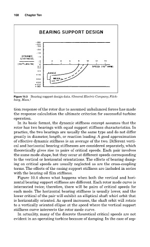
Figure 10.3 Bearing support design data. (General Electric Company, Fitch-
burg, Mass.)
tion response of the rotor due to assumed unbalanced forces has made
the response calculation the ultimate criterion for successful turbine
operation.
In its basic format, the dynamic stiffness concept assumes that the
rotor has two bearings with equal support stiffness characteristics. In
practice, the two bearings are usually the same type and do not differ
greatly in diameter, length, or reaction loading. A good approximation
of effective dynamic stiffness is an average of the two. Different verti-
cal and horizontal bearing stiffnesses are considered separately, which
theoretically gives rise to pairs of critical speeds. Each pair involves
the same mode shape, but they occur at different speeds corresponding
to the vertical or horizontal orientations. The effects of bearing damp-
ing on critical speeds are usually neglected as are the cross-coupling
terms. The effects of the casing support stiffness are included in series
with the bearing oil film stiffness.
Figure 10.4 shows what happens when both the vertical and hori-
zontal bearing support stiffness are different. Each rotor mode curve is
intersected twice; therefore, there will be pairs of critical speeds for
each mode. The horizontal bearing stiffness is usually lower, and the
lower critical of the pair will exhibit an elliptical shaft whirl orbit that
is horizontally oriented. As speed increases, the shaft orbit will rotate
to a vertically oriented ellipse at the speed where the vertical support
stiffness curve intersects the rotor mode curve.
In actuality, many of the discrete theoretical critical speeds are not
evident in an operating turbine because of damping. In the case of sep-