
Page 188 - Steam Turbines Design, Applications, and Rerating
P. 188
Rotor Dynamics Technology 167
culated and plotted as a function of assumed dynamic stiffness at the
journal surfaces. Special response tests were then run on a number of
production turbines by installing unbalanced weights in the rotors and
identifying the critical speeds by the shaft response amplitudes. Mode
shape indications were inferred from the relative phase relationships
of the measured shaft amplitudes. Having obtained the actual critical
speeds, the effective dynamic stiffnesses of the total support systems
could be derived from the rotor dynamic stiffness curves.
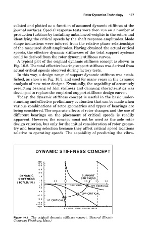
A typical plot of the original dynamic stiffness concept is shown in
Fig. 10.2. The total effective bearing support stiffness was derived from
actual critical speeds observed during factory tests.
In this way, a design range of support dynamic stiffness was estab-
lished, as shown in Fig. 10.3, and used for many years in the dynamic
analysis of new rotor designs. Eventually, the capability of accurately
predicting bearing oil film stiffness and damping characteristics was
developed to replace the empirical support stiffness design curves.
Today, the dynamic stiffness concept is useful in the basic under-
standing and effective preliminary evaluation that can be made when
various combinations of rotor geometries and types of bearings are
being considered. The separate effects of rotor changes and the use of
different bearings on the placement of critical speeds is readily
apparent. However, the concept must not be used as the sole rotor
design criterion, but only for the initial consideration of rotor geome-
try and bearing selection because they affect critical speed locations
relative to operating speeds. The capability of predicting the vibra-
Figure 10.2 The original dynamic stiffness concept. (General Electric
Company, Fitchburg, Mass.)