
Page 187 - Steam Turbines Design, Applications, and Rerating
P. 187
166 Chapter Ten
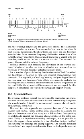
Figure 10.1 Impulse type steam turbine rotor model with mass stations iden-
tified. (General Electric Company, Fitchburg, Mass.)
and the coupling flanges and the gyroscopic effects. The calculation
proceeds, station by station, from one end of the rotor to the other. At
each station, the moment, the shear force, the slope, and the deflection
are calculated for an assumed frequency of vibration as functions of the
initial boundary conditions. The assumed frequency is varied until the
boundary conditions at the last station are satisfied. The assumed fre-
quency then equals the natural frequency.
External stiffness and damping are introduced at the journal loca-
tions. Unbalanced weights can then be added at any location along the
rotor, and a vibration response calculation can be made.
For a number of years following the development of Prohl’s method,
the knowledge of bearing oil film and support characteristics was
uncertain. The capability of making bearing analyses lagged behind
the rotor analyses. Because of this, efforts were made to evaluate the
rotor support characteristics and their effect on natural frequencies. In
the mid-1950s, the dynamic stiffness concept was developed for this
purpose. It considered the combined bearing and support system.
10.2 Dynamic Stiffness
The dynamic stiffness concept was developed to emphasize the crucial
role that rotor support characteristics have in determining the system
vibration behavior. It is still in use today and is commonly referred to
as the critical speed map.
The need for this approach was apparent because of the circum-
stances that existed. Prohl’s method made it possible to calculate the
dynamic characteristics of the rotor, but it did not have the capability
to analytically predict the dynamic characteristics of the rotor sup-
ports. Using an impedance-matching technique, it was possible to
derive the support characteristics for a line of turbine designs that had
the same type of bearings and casing supports. The method combined
the analytical and experimental results. Rotor critical speeds were cal-