
Page 276 - Steam Turbines Design, Applications, and Rerating
P. 276
Transmission Elements for High-Speed Turbomachinery 255
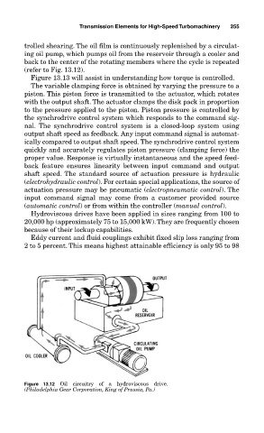
trolled shearing. The oil film is continuously replenished by a circulat-
ing oil pump, which pumps oil from the reservoir through a cooler and
back to the center of the rotating members where the cycle is repeated
(refer to Fig. 13.12).
Figure 13.13 will assist in understanding how torque is controlled.
The variable clamping force is obtained by varying the pressure to a
piston. This piston force is transmitted to the actuator, which rotates
with the output shaft. The actuator clamps the disk pack in proportion
to the pressure applied to the piston. Piston pressure is controlled by
the synchrodrive control system which responds to the command sig-
nal. The synchrodrive control system is a closed-loop system using
output shaft speed as feedback. Any input command signal is automat-
ically compared to output shaft speed. The synchrodrive control system
quickly and accurately regulates piston pressure (clamping force) the
proper value. Response is virtually instantaneous and the speed feed-
back feature ensures linearity between input command and output
shaft speed. The standard source of actuation pressure is hydraulic
(electrohydraulic control). For certain special applications, the source of
actuation pressure may be pneumatic (electropneumatic control). The
input command signal may come from a customer provided source
(automatic control) or from within the controller (manual control).
Hydroviscous drives have been applied in sizes ranging from 100 to
20,000 hp (approximately 75 to 15,000 kW).They are frequently chosen
because of their lockup capabilities.
Eddy current and fluid couplings exhibit fixed slip loss ranging from
2 to 5 percent. This means highest attainable efficiency is only 95 to 98
Figure 13.12 Oil circuitry of a hydroviscous drive.
(Philadelphia Gear Corporation, King of Prussia, Pa.)