
Page 278 - Steam Turbines Design, Applications, and Rerating
P. 278
Transmission Elements for High-Speed Turbomachinery 257
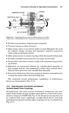
Figure 13.14 Oil passageways to each set of disk surfaces in a hydro-
viscous drive. (Philadelphia Gear Corporation, King of Prussia, Pa.)
■ Provide instantaneous response upon command.
■ Transmit torque in either direction.
■ Allow prime mover to be started under no load. Eliminate the need
for reduced voltage starting and expensive electrical accessories
when using synchronous motors.
■ Allow prime mover to remain running while disconnected from load.
■ Provide controlled acceleration for very large inertia loads.
■ Protect drive train from excessive loads with automatic torque limit-
ing feature.
■ Represent an economical solution for variable-speed operation of
fans, pumps, blowers, and compressors, rather than wasteful throt-
tling for those processes with variable-flow demands.
■ Extend fan blade liner life when running in abrasive atmospheres by
varying fan speed rather than throttling flow.
The estimated overall performance capabilities of hydroviscous
drives are represented in Fig. 13.15.
13.5 Hydrodynamic Converters and Geared
Variable-Speed Turbo Couplings
Hydrodynamic and other proven mechanical components are com-
bined in the design of such variable-speed devices as the Voith Trans-
mission Company’s VORECON, Fig. 13.16. The power savings that can
be realized from these multistage variable-speed drives and from
hydrodynamic geared variable-speed couplings can be visualized from
Fig. 13.17.