
Page 277 - Steam Turbines Design, Applications, and Rerating
P. 277
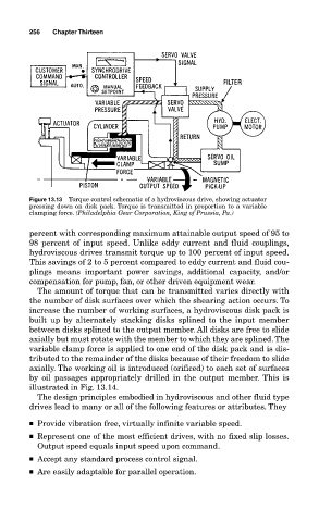
256   Chapter Thirteen


            Figure 13.13 Torque control schematic of a hydroviscous drive, showing actuator
            pressing down on disk pack. Torque is transmitted in proportion to a variable
            clamping force. (Philadelphia Gear Corporation, King of Prussia, Pa.)

            percent with corresponding maximum attainable output speed of 95 to
            98 percent of input speed. Unlike eddy current and fluid couplings,
            hydroviscous drives transmit torque up to 100 percent of input speed.
            This savings of 2 to 5 percent compared to eddy current and fluid cou-
            plings means important power savings, additional capacity, and/or
            compensation for pump, fan, or other driven equipment wear.
              The amount of torque that can be transmitted varies directly with
            the number of disk surfaces over which the shearing action occurs. To
            increase the number of working surfaces, a hydroviscous disk pack is
            built up by alternately stacking disks splined to the input member
            between disks splined to the output member. All disks are free to slide
            axially but must rotate with the member to which they are splined. The
            variable clamp force is applied to one end of the disk pack and is dis-
            tributed to the remainder of the disks because of their freedom to slide
            axially. The working oil is introduced (orificed) to each set of surfaces
            by oil passages appropriately drilled in the output member. This is
            illustrated in Fig. 13.14.
              The design principles embodied in hydroviscous and other fluid type
            drives lead to many or all of the following features or attributes. They

            ■ Provide vibration free, virtually infinite variable speed.
            ■ Represent one of the most efficient drives, with no fixed slip losses.
              Output speed equals input speed upon command.
            ■ Accept any standard process control signal.
            ■ Are easily adaptable for parallel operation.