
Page 59 - Steam Turbines Design, Applications, and Rerating
P. 59
40 Chapter Two
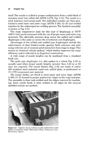
itself. The nozzle is milled to proper configuration from a solid block of
stainless steel (hot rolled 405 ASTM A-276, Fig. 2.13). The result is a
total stainless steel steam path. The individual nozzles are then posi-
tioned to steel inner and outer rings (ASTM A-283, Gr. D) and welded
together by the submerged arc welding process. The finished assembly
is shown in Fig. 2.14.
The stage temperature limit for this type of diaphragm is 750°F
(400°C) but can be increased with the use of proper inner and outer ring
materials. The allowable pressure drop across the milled and welded
diaphragm is the same as across the investment cast diaphragms.
Advantages of the milled and welded type diaphragms include the
achievement of close bucket-nozzle spacing (both entrance and exit)
along with the use of constant pitch diameters from stage to stage. This
results in “residual velocity pickup,” which further improves the stage
efficiency and is referred to as flugelized construction.
A wide range of nozzle heights can be machined from a standard
block size.
The spoke type diaphragm (i.e., like spokes in a wheel, Fig. 2.15) is
usually used when larger nozzle heights (greater than 3.25 in or 83
mm) are required. The nozzle blades (Fig. 2.16) are made of either
405 stainless steel material (sand cast, milled plate, or preformed) or
17-4 PH investment cast material.
The nozzle blades are fitted to steel inner and outer rings (ASTM
A-283, Gr. D) located in proper position by ridges on the rings and pins.
The assembly is then tack-welded and the ridges removed by machin-
ing. Each nozzle blade is then welded at all edges by the manual
shielded electric arc method.
Figure 2.13 Impulse steam turbine nozzles milled from solid
blocks of stainless steel. (Mitsubishi Heavy Industries, Ltd.,
Hiroshima, Japan)