
Page 62 - Steam Turbines Design, Applications, and Rerating
P. 62
Turbine Casing and Major Stationary Components 43
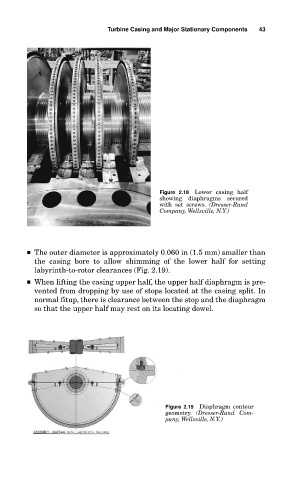
Figure 2.18 Lower casing half
showing diaphragms secured
with set screws. (Dresser-Rand
Company, Wellsville, N.Y.)
■ The outer diameter is approximately 0.060 in (1.5 mm) smaller than
the casing bore to allow shimming of the lower half for setting
labyrinth-to-rotor clearances (Fig. 2.19).
■ When lifting the casing upper half, the upper half diaphragm is pre-
vented from dropping by use of stops located at the casing split. In
normal fitup, there is clearance between the stop and the diaphragm
so that the upper half may rest on its locating dowel.
Figure 2.19 Diaphragm contour
geometry. (Dresser-Rand Com-
pany, Wellsville, N.Y.)