
Page 67 - Steam Turbines Design, Applications, and Rerating
P. 67
48 Chapter Two
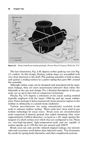
Figure 2.27 Steam leakoff and sealing principle. (Dresser-Rand Company, Wellsville, N.Y.)
The last illustration, Fig. 2.26, depicts carbon packing (see also Fig.
1.5, earlier). In this design, floating carbon rings are assembled with
very close clearance to the shaft. The packing assembly is held in place
and against a sealing surface by a garter spring that goes 360° around
the assembly.
Although carbon rings can be designed and manufactured for mini-
mum leakage, they are more maintenance-intensive than either the
labyrinth or dry gas seal design. For a detailed description of dry gas
seals, see an up-to-date text on compressor technology.
Finally, Fig. 2.27 depicts a schematic of the steam sealing method
typically employed with the larger (1000 hp and up) steam turbine
sizes. Steam leakage is led to successively lower pressure regions in the
turbine or, ultimately, to a gland steam condenser.
Turbine manufacturers are using commercially available brush
seals to enhance turbine sealing. These seals have been used in gas
turbine technology for many years. Brush seals are circumferential
seals comprised of densely packed, fine nickel chromium alloy wires
(approximately 0.006-in diameter), arrayed on a 45° angle against the
tangent of a shaft surface over which they are configured to run. These
are very-high-tip-speed, high-temperature-seals and are capable of
surface speeds up to 1100 ft/s (feet per second) and 1200°F.
Brush seals not only provide reduced original leakage, but tolerate
rubs and transients much better than labyrinth seals. This eliminates
the needs for spring-back labyrinths and other complicated systems.